
Image pickup lens

a technology of image pickup and lens, which is applied in the field of image pickup lenses, can solve the problems of insufficient brightness, insufficient response, and severe demand for downsizing and thinning of the imaging devices built in,

Active Publication Date: 2014-08-26
TOKYO VISIONARY OPTICS CO LTD
View PDF5 Cites 6 Cited by
  • Summary
  • Abstract
  • Description
  • Claims
  • Application Information

AI Technical Summary

Benefits of technology

The present invention aims to solve problems in the prior art by providing an image pickup lens that is smaller, thinner, has a smaller F value, corrects various aberrations well, has a wider angle of field, and is cost-effective.

Problems solved by technology

Along with the increasing demands for thinning of portable terminals from viewpoint of user-friendliness and design, demands for downsizing and thinning of the imaging devices built therein are also becoming severe.
However, the half angle of field of the lens is 30 to 31°, which is insufficient for answering to the demand of wider angle of field.
According to the image pickup lens taught in Patent Document 4, downsizing is also comparatively realized, but the F value thereof is 3.2, which means that sufficient brightness is not achieved.
As described, it was not possible according to the prior art lenses to answer to the demands of downsizing, wider angle of field and small F value at the same time.

Method used


Image

  • Image pickup lens
  • Image pickup lens
  • Image pickup lens

Examples


embodiment 6

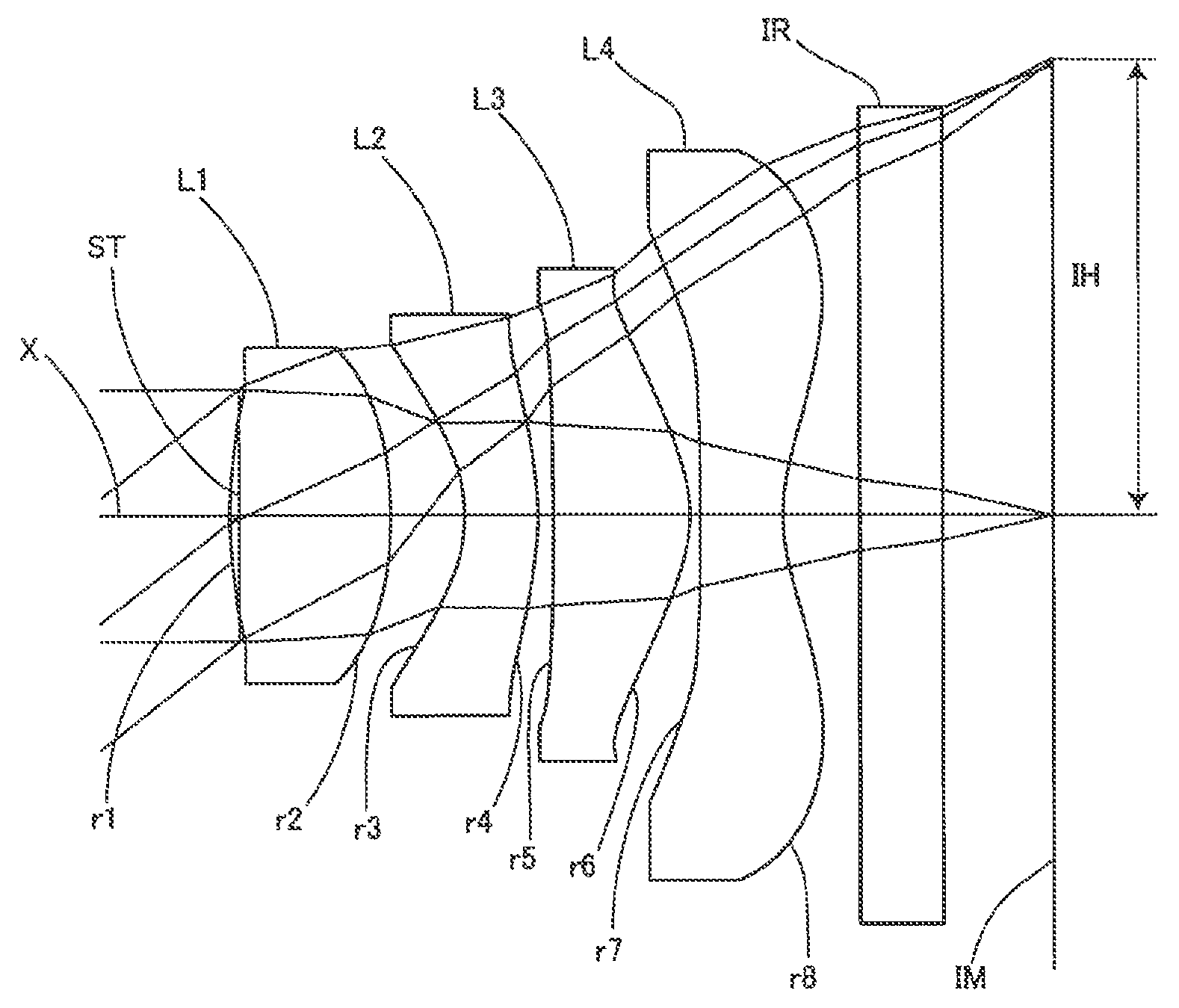
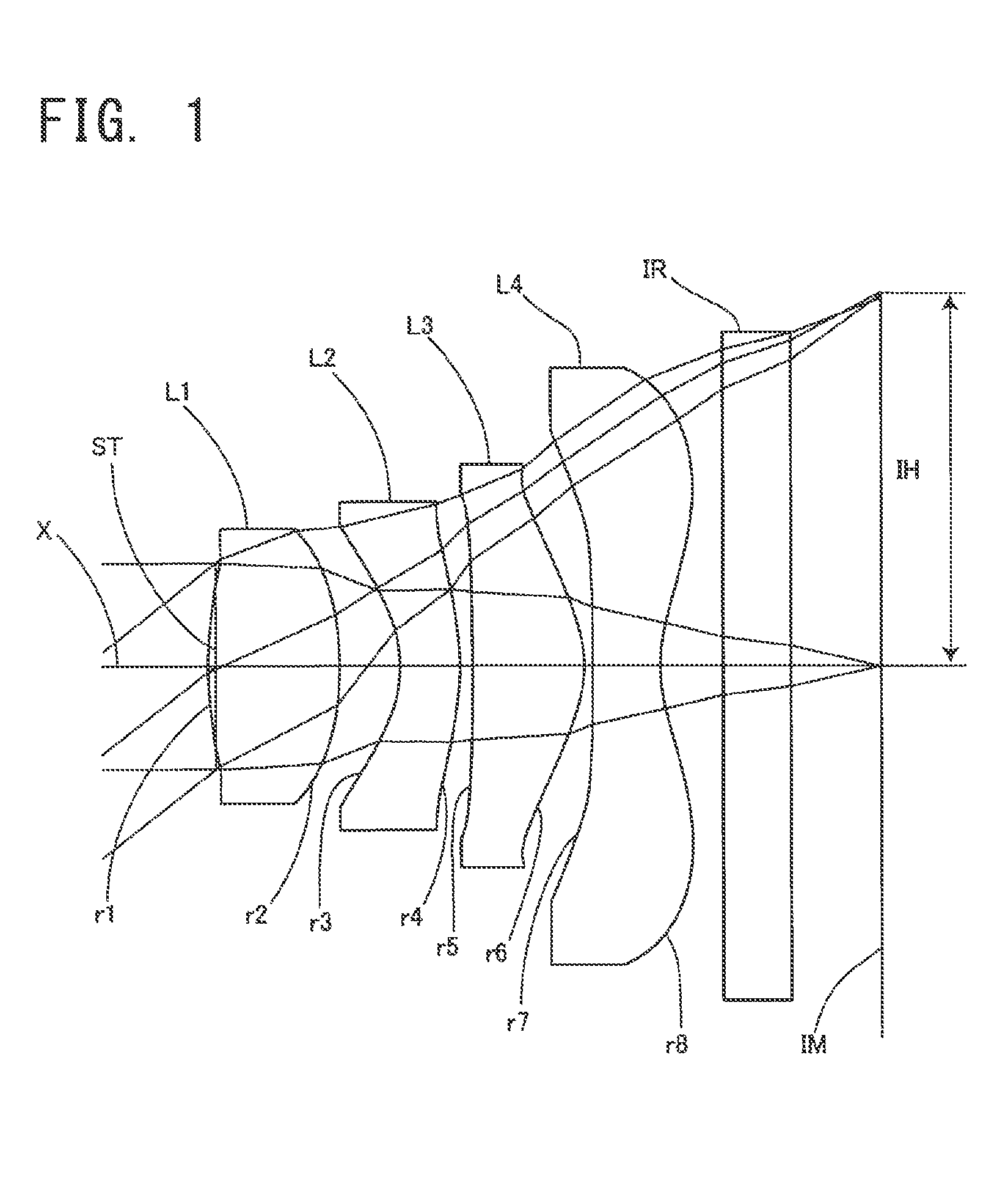
[0063]In Embodiment 6, the first lens L1 and the fourth lens L4 are formed of cycloolefin polymer, the second lens L2 is formed of polycarbonate, and the third lens L3 is formed of cycloolefin copolymer.

[0064]By adopting plastic materials for all the lenses, it becomes possible to realize stable mass production and facilitate cost reduction.

[0065]The image pickup lens according to the present invention satisfies the following conditional expressions.

0.6<f1 / f<0.8  (1)

f3<f1  (2)

0.9<f3 / |f4|<1.10  (3)

0.7<|f2| / f<1.2  (4)

0.28<Bf / TTL<0.35  (5)

0.7<IH / f<0.80  (6)

2.2<f / EP<2.5  (7)

where[0066]f: focal length of the overall optical system of the image pickup lens[0067]f1: focal length of the first lens[0068]f2: focal length of the second lens[0069]f3: focal length of the third lens[0070]f4: focal length of the fourth lens[0071]Bf: distance on the optical axis from the image side surface of the fourth lens to the image plane (distance calculated through air)[00...

embodiment 1

[0078

[0079]Basic lens data will be shown in Table 1 below.

[0080]

TABLE 1Embodiment 1Unit mmf = 2.143Fno = 2.408ω = 36.91°Surface dataSurfaceRefractiveAbbe No.Surface No. iCurvature radius rdistance dindex Ndνd(Object surface)InfinityInfinityStopInfinity−0.0341*1.46850.5861.53462256.16032*−1.48720.2683*−0.56550.271.63548923.91144*−1.24110.0545*−8.71350.49881.53462256.16036*−0.51540.03817*−106.54540.31.53462256.16038*0.56870.289 Infinity0.31.51479854.198310 Infinity0.4244Image PlaneInfinitySingle lens dataLensStart surfaceFocal length111.478923−1.9222350.999247−1.0528Aspheric dataFirst surfaceSecond surfaceThird surfaceFourth surfacek0−26.3−0.311−1.63A4−2.179E−01−1.304E+006.668E−018.918E−03A6−7.746E−011.496E+00−2.500E+002.435E+00A82.453E+00−1.059E+003.525E+01−1.255E+01A10−1.367E+01−3.647E+00−1.084E+024.448E+01A120.000E+001.447E+001.227E+02−7.945E+01A140.000E+000.000E+000.000E+005.302E+01A160.000E+000.000E+000.000E+000.000E+00Fifth surfaceSixth surfaceSeventh surfaceEighth surfacek0−4.8...

embodiment 2

[0084

[0085]Basic lens data will be shown in Table 2 below.

[0086]

TABLE 2Embodiment 2Unit mmf = 2.113Fno = 2.414ω = 37.31°Surface dataSurfaceRefractiveAbbe No.Surface No. iCurvature radius rdistance dindex Ndνd(Object surface)InfinityInfinityStopInfinity−0.031*1.530.5831.53462256.16032*−1.40530.2693*−0.55420.271.63548923.91144*−1.17670.04835*−6.30970.51931.53462256.16036*−0.47660.027*−99.00840.31.53462256.16038*0.5244920.289 Infinity0.31.51479854.198310 Infinity0.4272Image planeInfinitySingle lens dataLensStart surfaceFocal length111.467523−1.9697350.932347−0.9717Aspheric dataFirst surfaceSecond surfaceThird surfaceFourth surfacek0−21.8−0.34−2.2A4−2.260E−01−1.305E+007.278E−013.080E−02A6−8.538E−011.510E+00−2.477E+002.405E+00A82.592E+00−1.029E+003.497E+01−1.258E+01A10−1.406E+01−3.746E+00−1.082E+024.436E+01A120.000E+001.447E+001.227E+02−7.945E+01A140.000E+000.000E+000.000E+005.302E+01A160.000E+000.000E+000.000E+000.000E+00Fifth surfaceSixth surfaceSeventh surfaceEighth surfacek0−4.580−6....


PUM


Abstract

An image pickup lens having a relatively wide angle of field with various aberrations preferably corrected and having a small F-value is achieved. The image pickup lens is composed of, in order from an object side, an aperture stop, a first lens of a biconvex shape having a refractive power, a second lens of a meniscus shape having a negative refractive power with a concave surface facing the object side near the optical axis, a third lens of a meniscus shape having a positive refractive power with a concave surface facing the object side near the optical axis, and a fourth lens of a biconcave shape having a negative refractive power near the optical axis, wherein the image pickup lens satisfies a following conditional expression (1):0.6<f1 / f<0.8  (1)where f1 represents a focal length of the first lens, and f represents a focal length of the overall image pickup lens.

Description

[0001]The present application is based on and claims priority of Japanese patent application No. 2012-011272 filed on Jan. 23, 2012, the entire contents of which are hereby incorporated by reference.BACKGROUND OF THE INVENTION[0002]1. Field of the Invention[0003]The present invention relates to an image pickup lens for forming an image of an object on a solid-state imaging element such as a CCD sensor, a C-MOS sensor and the like used in a small-sized imaging device, and especially relates to an image pickup lens built into an imaging device mounted on a portable terminal such as a cellular phone or a smartphone, a PDA (Personal Digital Assistance), a game machine, an information terminal such as a personal computer, where downsizing and thinning are pursued.[0004]2. Description of the Related Art[0005]Recently, the market for portable terminals having imaging devices is increasingly expanding. Most portable terminals are equipped with a camera function, and currently, a majority of...

Claims


Application Information

Patent Timeline
Patent Type & Authority Patents(United States)
IPC IPC(8): G02B13/18G02B9/34G02B13/00
CPCG02B9/34G02B13/004
Inventor HASHIMOTO, MASAYA
Owner TOKYO VISIONARY OPTICS CO LTD
Learn More