Combined xylene isomerization and transalkylation process unit

a technology of xylene isomerization and transalkylation, which is applied in the direction of separation processes, combustion-air/fuel-air treatment, carburettant air, etc., can solve the problem of adding significant capital costs to the aromatic complex

Active Publication Date: 2014-09-02
UOP LLC
View PDF7 Cites 16 Cited by
  • Summary
  • Abstract
  • Description
  • Claims
  • Application Information

AI Technical Summary

Problems solved by technology

The duplication of equipment, such as the separators, gas recycle compressors, and fractionation columns, to process streams containing similar components, although in different amounts, adds significant capital cost to the aromatics complex.

Method used


Image

  • Combined xylene isomerization and transalkylation process unit
  • Combined xylene isomerization and transalkylation process unit
  • Combined xylene isomerization and transalkylation process unit

Examples


Embodiment Construction

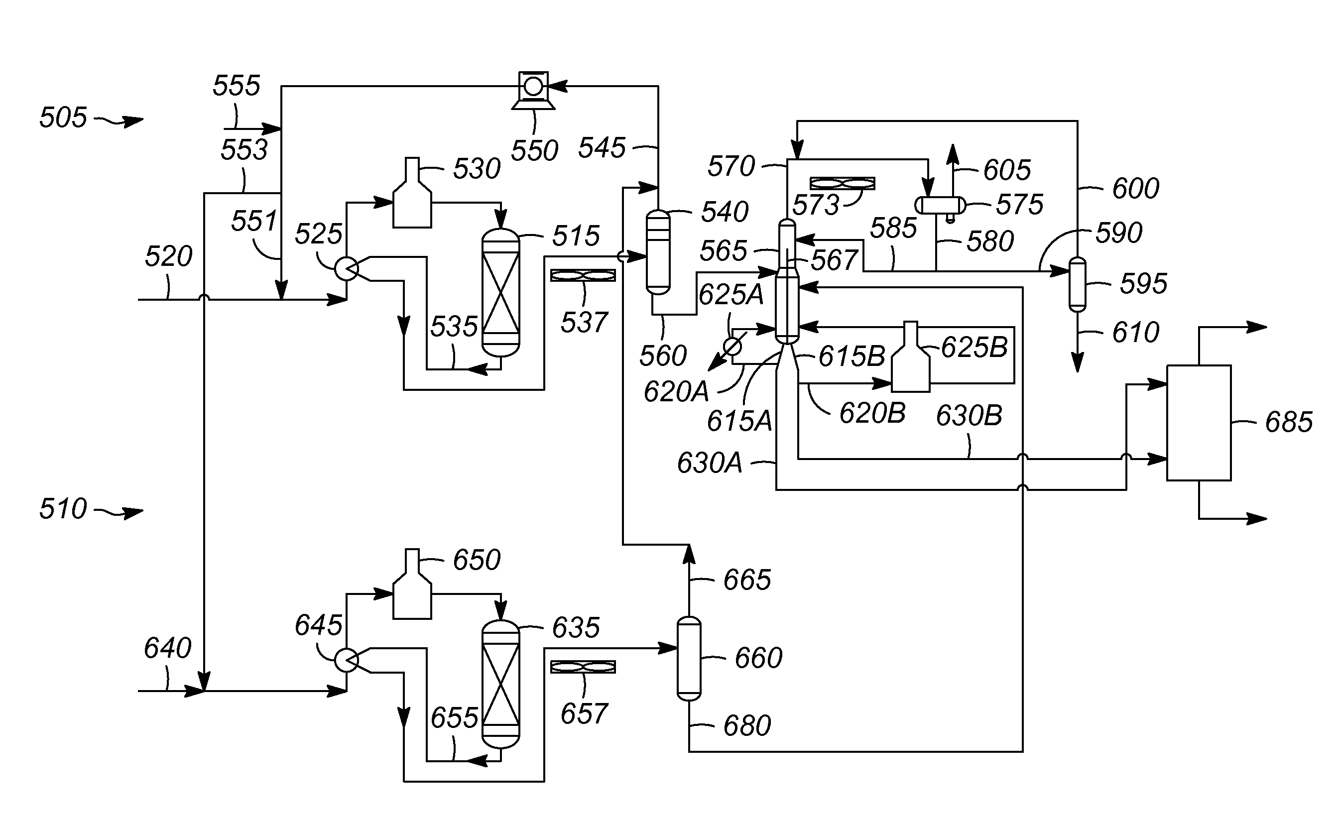
[0015]The xylene isomerization process unit and the transalkylation process units are combined in the present invention. A single detoluene fractionation column can be shared by the two units. In some embodiments, the separator and recycle gas compressor can also be shared. The removal of one the fractionation columns, as well as one of the separators and one of the gas recycle compressors in some embodiments, significantly reduces the capital cost of the unit.

[0016]The development of new transalkylation catalysts, which allow the transalkylation reactor to operate at lower pressures, makes the sharing of equipment between the isomerization section and the transalkylation section practical.

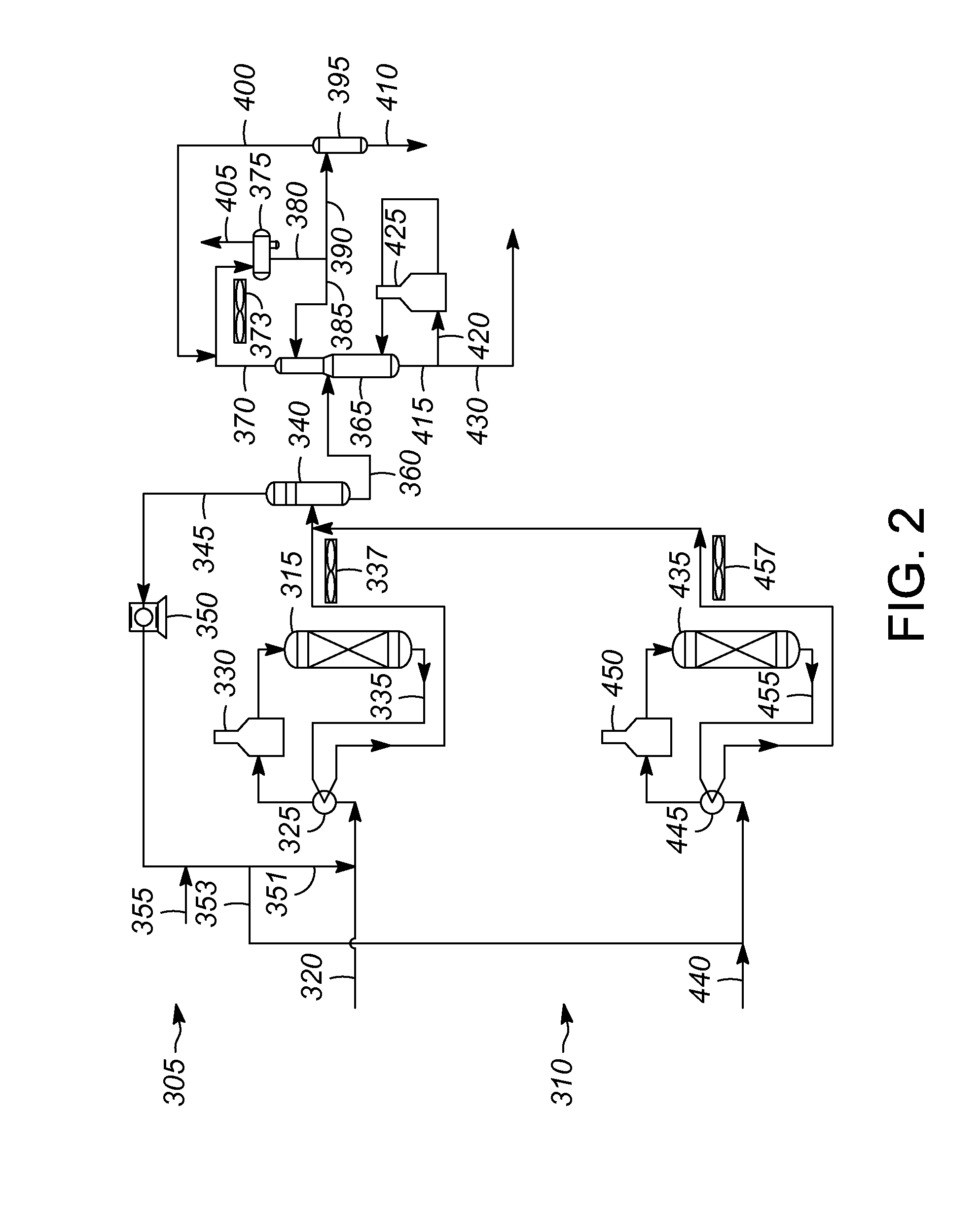
[0017]In one embodiment shown in FIG. 2, the isomerization and transalkylation reactor zones are independent, i.e., each has its own reactor feed heat exchanger, charge heater, reactor, and product condenser. The effluent from each reactor section is sent to a common separator.

[0018]The isomerizat...


PUM

PropertyMeasurementUnit
liquidaaaaaaaaaa
pressureaaaaaaaaaa
pressuresaaaaaaaaaa

Abstract

The xylene isomerization process unit and the transalkylation process units are combined in the present invention. A fractionation column can be shared by the two units, reducing the capital cost of the complex. In some embodiments, a split shell fractionation column and a split separator can be used.

Description

CROSS-REFERENCE TO RELATED APPLICATION[0001]This application claims benefit of U.S. Provisional Application No. 61 / 578,609 which was filed on Dec. 21, 2011.BACKGROUND OF THE INVENTION[0002]A typical aromatics complex includes a xylene isomerization unit and a transalkylation unit. The xylene isomerization unit and the transalkylation unit are completely separate process units, each with its own separator, recycle gas compressor, and fractionation column.[0003]An example of a current aromatics complex is shown in FIG. 1. The complex includes a xylene isomerization unit 5 and the transalkylation unit 10. The isomerization unit 5 has an isomerization reactor 15. The feed 20 is pre-heated in a heat exchanger 25 and further heated in a charge heater 30 before entering the isomerization reactor 15. The effluent 35 from the isomerization reactor 15 is sent to the heat exchanger 25, the condenser 37, and then to the separator 40. The overhead 45 from the separator 40 is sent to a recycle ga...

Claims


Application Information

Patent Timeline
Patent Type & Authority Patents(United States)
IPC IPC(8): C07C6/12C07C15/08
CPCB01D3/141C07C5/2702C07C6/06C07C5/2729C07C6/12C07C7/04C07C5/2732C07C15/08B01J8/04
Inventor CORRADI, JASON T.ABLIN, DAVID W.LIU, DAVID W.
Owner UOP LLC
Why Eureka
Try Eureka