
Hinged dual panel electronic device

a dual-panel electronic device and a technology for curved panels, applied in the direction of instruments, doors/window fittings, constructions, etc., to achieve the effect of constant resistan

Active Publication Date: 2014-09-09
INTEL CORP
View PDF76 Cites 20 Cited by
  • Summary
  • Abstract
  • Description
  • Claims
  • Application Information

AI Technical Summary

Benefits of technology

This patent is about an electronic device that has two parts that can rotate 360 degrees around each other. They are connected by a flexible member that passes through both parts. This allows for smooth movement between the parts without any sudden stops or changes in resistance. This design makes it easy to use and has improved performance compared to other devices.

Problems solved by technology

The design challenges for such hinges include providing full rotation while maintaining substantially constant contact or a minimal gap between the hinged modules.

Method used


Image

  • Hinged dual panel electronic device
  • Hinged dual panel electronic device
  • Hinged dual panel electronic device

Examples


Embodiment Construction

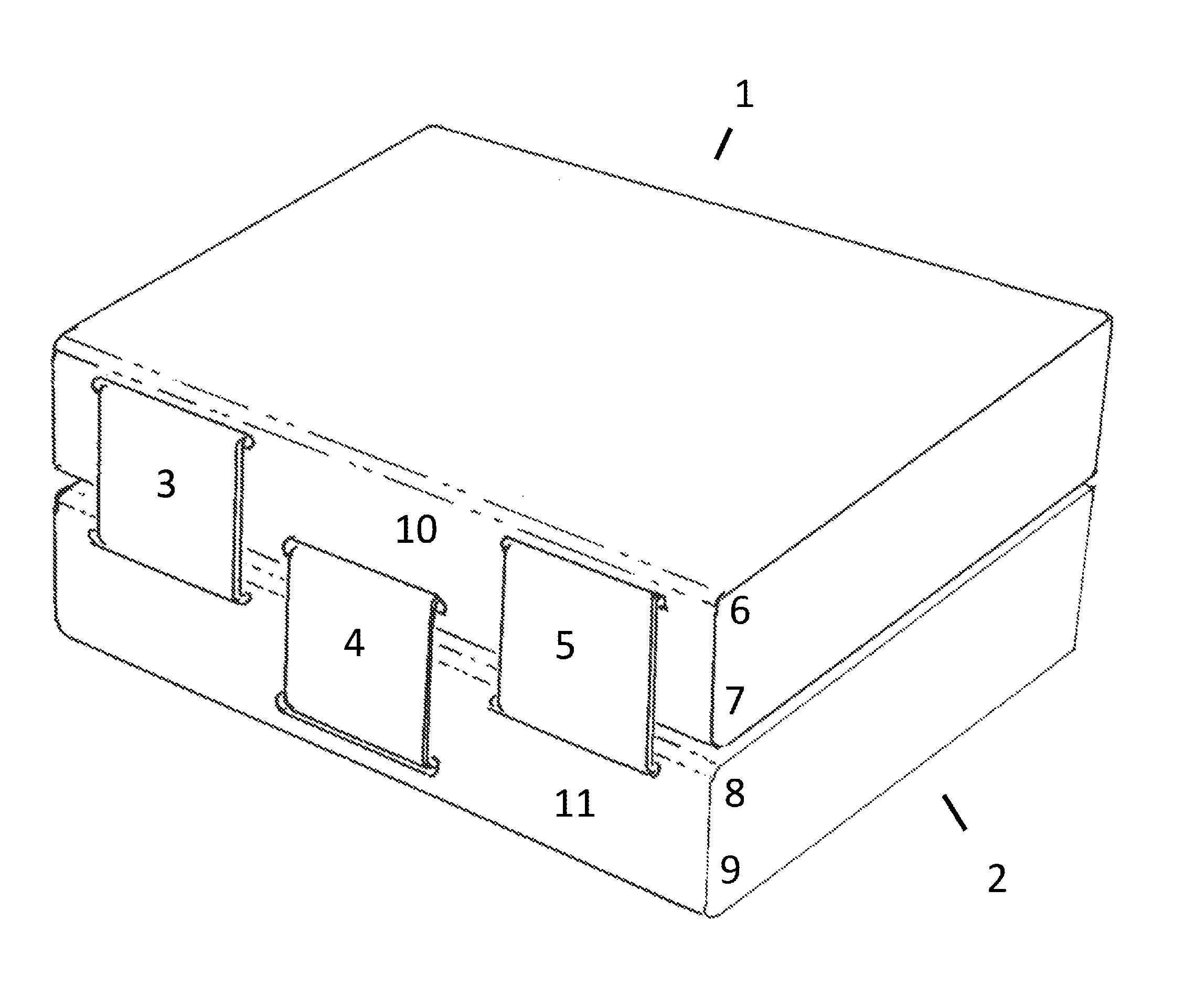
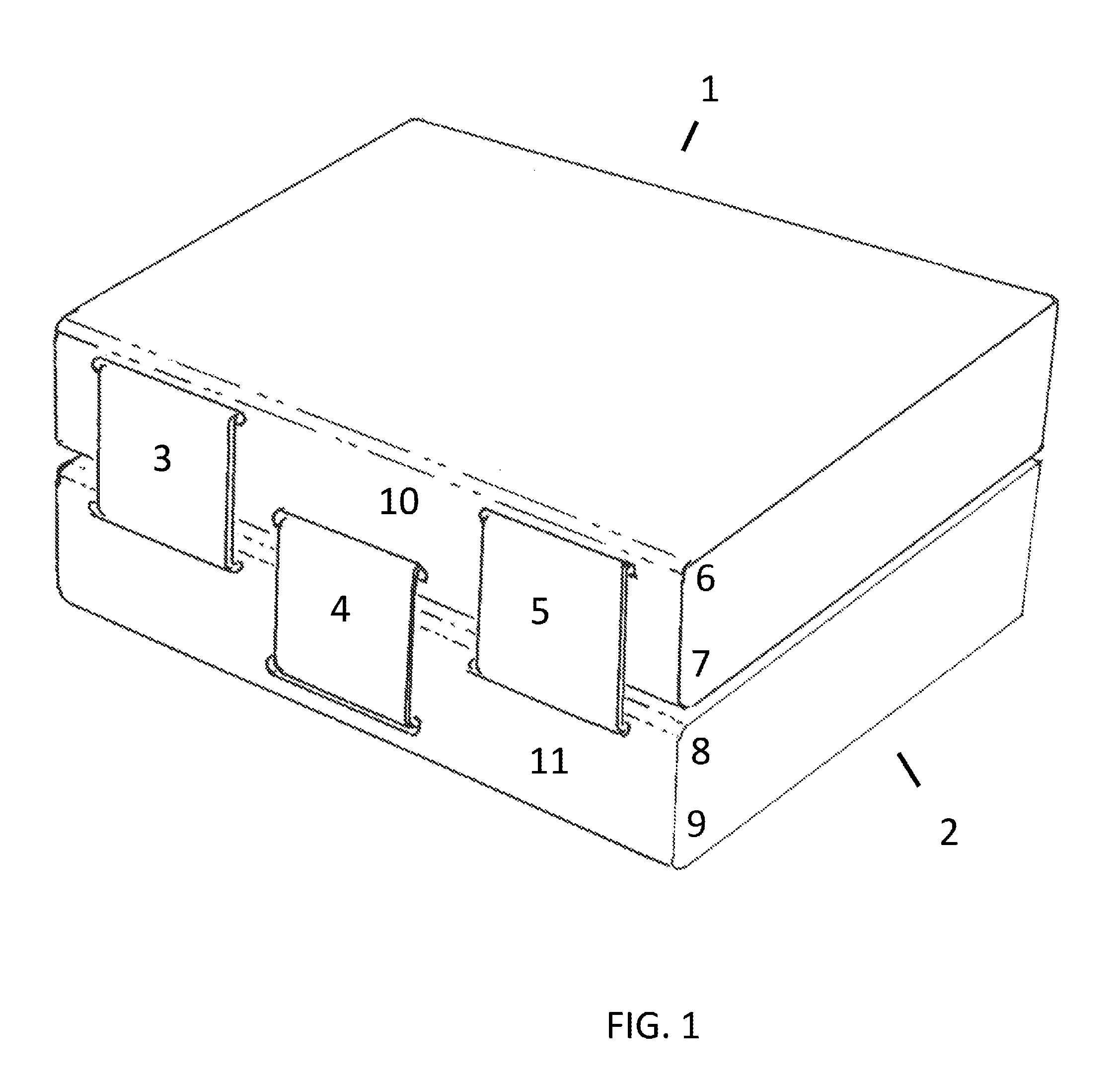
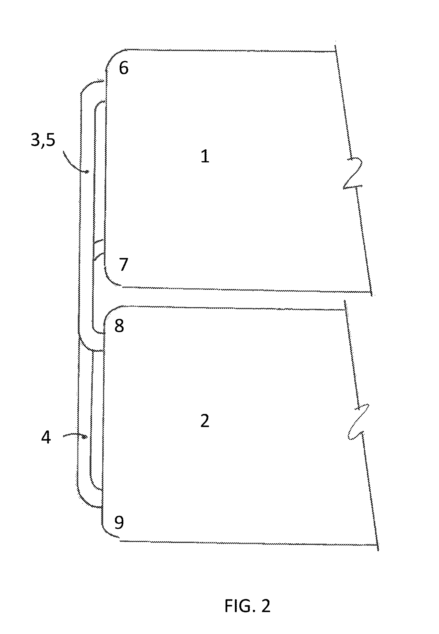
[0023]FIG. 1 illustrates a first electronic module 1 and a second electronic module 2. By way of the example, the two electronic modules may form a dual panel electronic book reader. In this embodiment, the electronic device can be held like a traditional paper book or can be folded back upon itself such that both displays are facing outward. The hinge mechanism that connects the two modules uses flexible members between the two modules that can support tension loads and allow for up to 360 degrees of rotation between the two modules, while maintaining substantially constant contact or close proximity between the hinged modules. In this embodiment, the hinge mechanism entry and exit points for attachment reside on the edges of the objects. The entry and exit points may reside on the hinge end, such that only one face of each module is covered. For example, in FIG. 1, the flexible straps 3 and 5 enter module 1 by the long edge 6 and enter the module 2 by the long edge 8 such that the...


PUM


Abstract

A electronic device includes a first housing body with a first hinged end, a first free end, and a first fastening surface between the first hinged end and the first free end. A second housing body has a second hinged end, a second free end, and a second fastening surface between the second hinged end and the second free end. A flexible member is fixed to the first fastening surface and passes though the first hinged end and through the second hinged end for connection to a sliding cartridge that is affixed to the second fastening surface. The sliding cartridge provides substantially constant resistance during 360° rotation between the first housing body and the second housing body.

Description

CROSS REFERENCE TO RELATED APPLICATIONS[0001]This application claims priority to U.S. Provisional Patent Application 61 / 350,472 filed Jun. 1, 2010, entitled “Enhanced Hinge”, the contents of which are incorporated herein by reference.FIELD OF THE INVENTION[0002]This invention relates generally to consumer electronic devices. More particularly, this invention relates to a dual panel electronic device with an optimized hinge.BACKGROUND OF THE INVENTION[0003]Dual panel electronic devices are known. There are ongoing efforts to improve the hinges that connect dual panel electronic devices. The design challenges for such hinges include providing full rotation while maintaining substantially constant contact or a minimal gap between the hinged modules. Ideally, the hinge mechanism produces a substantially constant resistance through rotation about an axis. Finally, bulky internal or external components should also be avoided.SUMMARY OF THE INVENTION[0004]A electronic device includes a fir...

Claims


Application Information

Patent Timeline
Patent Type & Authority Patents(United States)
IPC IPC(8): E05D1/00
CPCG06F1/1683G06F1/1681
Inventor JAUVTIS, NATHAN ISAIAHHOUDEK, II, PHILIP J.WILKINS, DAN PAGEMOISEYENKO, STAN
Owner INTEL CORP
Learn More