Cable and structure traversing trolleys

a technology of cable and structure, which is applied in the direction of hoisting equipment, elevators, load-engaging elements, etc., can solve the problems of riders' injuries, damage to loads, and unwanted consequences

Inactive Publication Date: 2019-05-16
TRUBLUE
View PDF0 Cites 9 Cited by
  • Summary
  • Abstract
  • Description
  • Claims
  • Application Information

AI Technical Summary

Problems solved by technology

This may result in unwanted consequences, such as: injuries to riders, damages to loads, damage to trolleys, damage to braking components, increased braking force due to unintended consequences (such as trolleys lifting and creating drag on cables or other components), and/or lost efficiencies (such as loads not arriving at the intended location because of irregularities in braking requiring time to retrieve the load and place the system back into service).
However, friction braking mechanisms may induce high wear to braking pads, sheave...

Method used


Image

  • Cable and structure traversing trolleys
  • Cable and structure traversing trolleys
  • Cable and structure traversing trolleys

Examples


Embodiment Construction

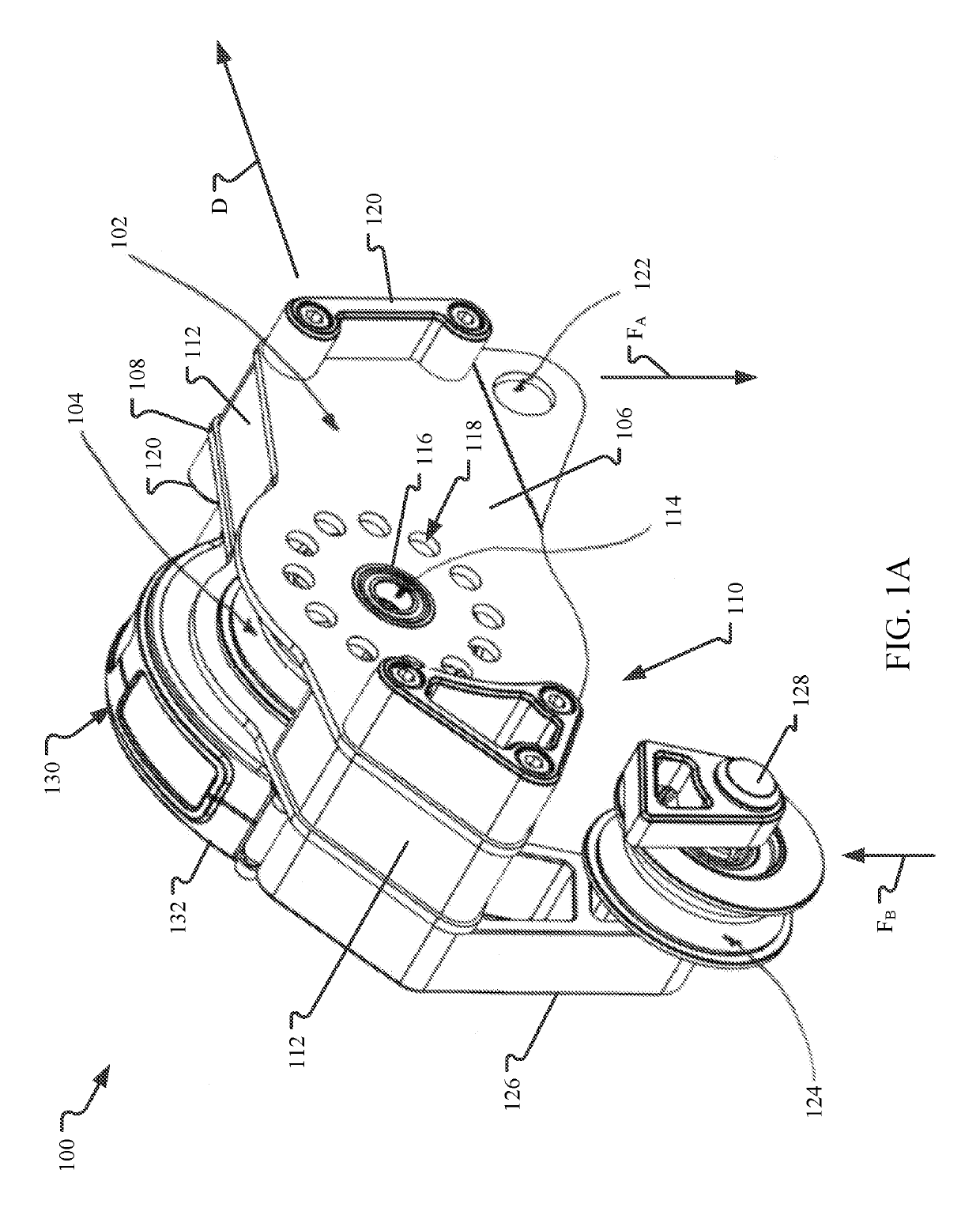
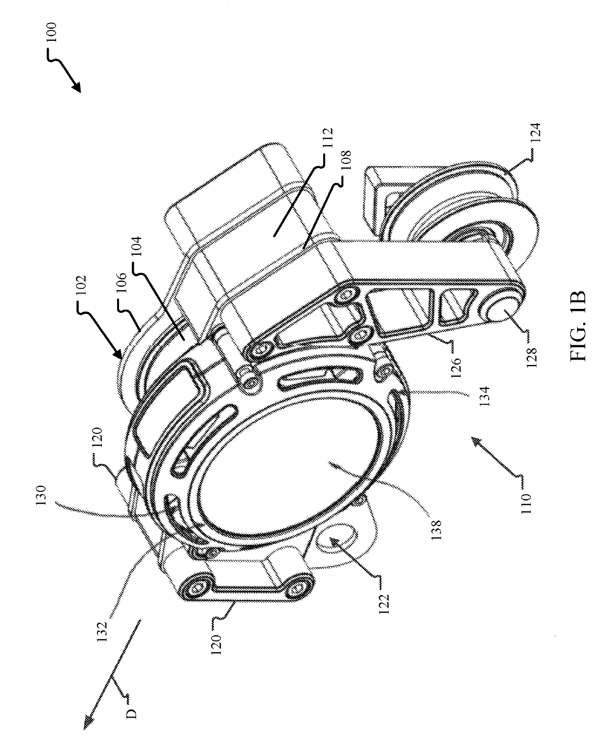
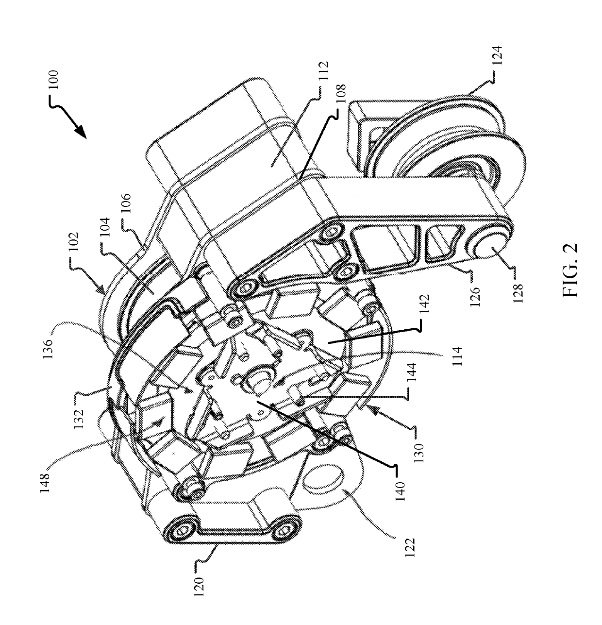
[0035]This disclosure describes examples of load carrying trolleys with eddy current braking mechanisms. In aspects, the eddy current braking mechanism is based at least in part on the centrifugal force generated by the rotation of one or more sheaves of the trolley as it traverses across the cable. These braking mechanisms enable for the resistance force generated by the braking mechanism to be dynamic (e.g., based at least partially on rotational speed) so that trolley speed along the cable is more constant across a wide variety of operating conditions (e.g., weight loads). In other aspects, the eddy current braking mechanism may generate a more constant resistance force so that the braking mechanism generates the same braking force for all trolleys and under all operating conditions. In either aspect, the trolley may include magnet and conductor configurations that increase the performance of the trolley. For example, a housing of the trolley may be formed as the conductive eleme...


PUM


Abstract

A trolley includes a housing, at least one sheave rotatably mounted at least partially within the housing, and a braking mechanism. The braking mechanism includes a rotor assembly coupled to the at least one sheave, at least one conductive element, and at least one magnetic element. The rotor assembly is rotatable with the at least one sheave, and when the rotor assembly rotates, the at least one conductive element overlaps with the at least one magnetic element based at least in part on a rotational speed of the rotor assembly.

Description

CROSS-REFERENCE TO RELATED APPLICATIONS[0001]This application claims priority to and the benefit of U.S. Provisional Patent Application No. 62 / 585,842, titled “CABLE AND STRUCTURE TRAVERSING TROLLEYS,” and filed Nov. 14, 2017, which is hereby incorporated by reference in its entirety.INTRODUCTION[0002]Cable and structure traversing trolleys are utilized in industrial and amusement applications, whereby suspended static cables enable a load or user to descend, gravitationally, from an upper support structure to a lower support structure. For example, in amusement applications, zip lines, alternatively written as “ziplines” or “zip-lines,” refer to a form of entertainment in which a rider traverses a wire or other cable from one point to another. Typically, trolleys that support the load or rider are designed to reduce rolling resistance while traversing the cable. As such, the slope of the cable at least partially defines the descent speed of the trolley. Under these circumstances, t...

Claims


Application Information

Patent Timeline
IPC IPC(8): B66B11/04B66D5/06B66D5/26B66B5/04B66B5/18B66B11/00
CPCB66B11/0438B66D5/06B66D5/26B66B5/044B66B5/18B66B11/0005B66C7/00A63G21/22B66C13/30
Inventor MCGOWAN, JOHN LEWIS
Owner TRUBLUE
Why Eureka
Try Eureka