Autofocusing device for microscopes and suitable autofocus aperture stops

a technology of autofocusing device and microscope, which is applied in the direction of measuring device, mounting device, instruments, etc., can solve the problem that the reflection produced there cannot strike the detector of the autofocusing devi

Active Publication Date: 2014-09-09
LEICA MICROSYSTEMS CMS GMBH
View PDF16 Cites 1 Cited by
  • Summary
  • Abstract
  • Description
  • Claims
  • Application Information

AI Technical Summary

Benefits of technology

[0019]The autofocus aperture stop proposed according to the invention thus not only limits the cross section of the measuring beam pencil to at most one semi-circular segment but also covers a large part of the other semi-circular segment and an area about the optical axis. In this way, axially close beams which lead to the above-mentioned first order reflections are largely prevented. The surface apices of the optical surfaces (lenses) present in the measuring beam path thus do not have the autofocus measuring beam running through them, with a result that no reflections produced there are able to strike the detector of the autofocusing device. As a result the signal-to-noise ratio of the measuring signal can be improved in favour of a highly precise measurement. This is particularly to the benefit of autofocused systems which use interfaces with a low level of reflection, such as the interface between cover glass and aqueous solution or Petri dish and aqueous solution, as a reference surface for holding the focus. The degree of reflection is only about 4 / 10th of 1% (=0.004), which is very much less than the degree of reflection on glass, which is about 4% (0.04). Hitherto conventional measures for reducing scattered light by means of additional optical components can be dispensed with.
[0035]The automatic selection of a suitable aperture stop and its use in the measuring beam path as a function of the microscope objective just used or its entry pupil diameter are advantageous. For this, the objectives used are detected by their characteristics in a motorised or automated microscope.

Problems solved by technology

The surface apices of the optical surfaces (lenses) present in the measuring beam path thus do not have the autofocus measuring beam running through them, with a result that no reflections produced there are able to strike the detector of the autofocusing device.

Method used


Image

  • Autofocusing device for microscopes and suitable autofocus aperture stops
  • Autofocusing device for microscopes and suitable autofocus aperture stops
  • Autofocusing device for microscopes and suitable autofocus aperture stops

Examples


Embodiment Construction

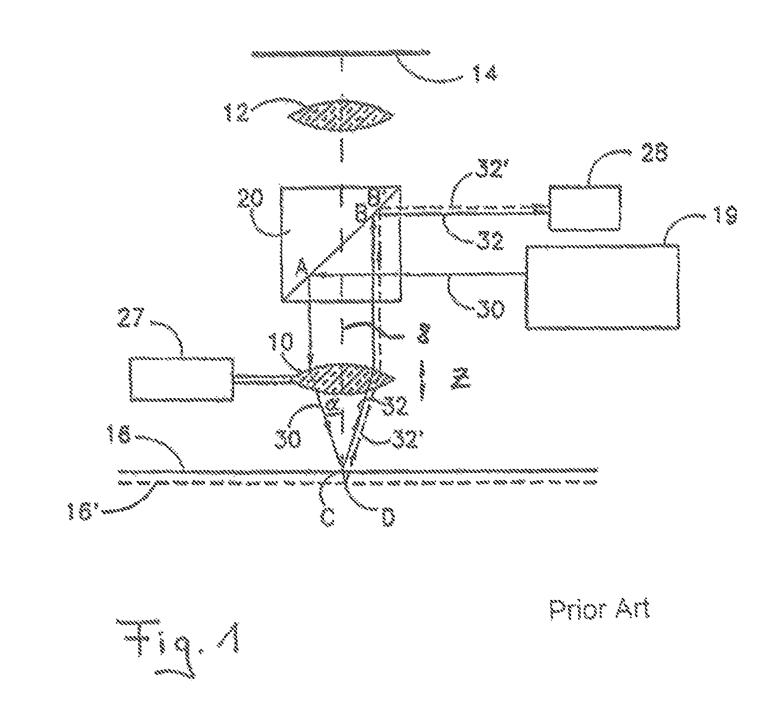
[0045]The triangulating autofocusing device according to FIG. 1 has already been discussed in detail in the introduction to the description.

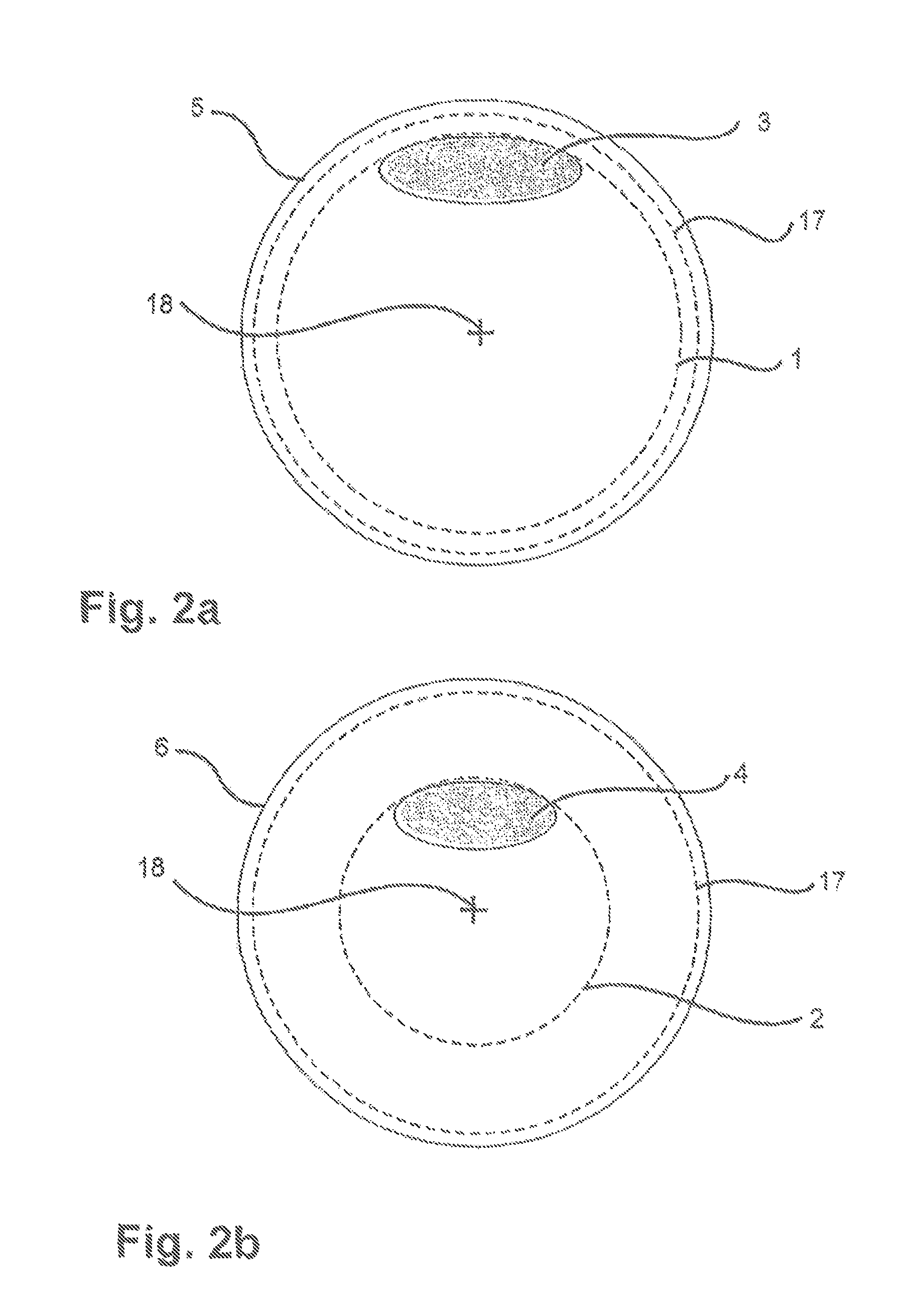
[0046]FIGS. 2a and 2b now show two different autofocus aperture stops 5 and 6 of the kind that may advantageously be used alternatively in a triangulating autofocusing device for a microscope in order to limit the cross section of a measuring beam pencil 17 used for autofocusing and running in the direction of the optical axis of the autofocusing device. For this purpose the autofocus aperture stop 5 comprises a highly decentred diaphragm opening 3 and the autofocus aperture stop 6 comprises a slightly decentred diaphragm opening 4. Each of the two diaphragm openings 3 and 4 is decentred at a spacing from the optical axis 18 of the autofocusing device or measuring beam pencil, so that each diaphragm opening 3 or 4 is located outside the said optical axis 18. In addition, for carrying out a triangulating autofocus measurement, each diaphragm open...


PUM


Abstract

The present invention relates to an autofocus aperture stop (5, 6) in a triangulating autofocusing device (21) for a microscope (40), wherein the autofocus aperture stop (5, 6) comprises at least one diaphragm opening (3, 4) with which a measuring beam pencil (34) used for the autofocusing and running in the direction of the optical axis (18) of the autofocusing device (21) can be limited in its cross section, wherein the diaphragm opening (3, 4) of the autofocus aperture stop (5, 6) is arranged in a decentred position at a spacing from the optical axis (18) of the autofocusing device (21), wherein a decentred autofocus measuring beam (36) can be generated by the diaphragm opening (3, 4) in one half of the cross section (17) of the measuring beam pencil (34).

Description

CROSS-REFERENCE TO RELATED APPLICATIONS[0001]This application claims priority to German Patent Application No. DE 10 2010 030 430.1 filed on Jun. 23, 2010, that is incorporated herein by reference in its entirety.FIELD OF THE INVENTION[0002]The present invention relates to an autofocus aperture stop or diaphragm in a triangulating autofocusing device for a microscope, wherein the aperture stop comprises at least one diaphragm opening and is configured so as to define the cross-section of a measuring beam pencil used for the autofocusing and running in the direction of the optical axis of the autofocusing device, as well as a triangulating autofocusing device for a microscope having an aperture stop of this kind for producing an autofocus measuring beam and autofocusing optical means, in order to generate a measuring pattern on an object by means of the autofocus measuring beam using an objective of the microscope.[0003]By a measuring pattern is meant for example a measuring spot or ...

Claims


Application Information

Patent Timeline
Patent Type & Authority Patents(United States)
IPC IPC(8): G01C21/02G02B21/00G02B21/24
CPCG02B21/241G02B21/245
Inventor KRUEGER, RALF
Owner LEICA MICROSYSTEMS CMS GMBH
Why Eureka
Try Eureka