Imaging device and imaging method
a technology of imaging device and white balance correction, which is applied in the direction of color signal processing circuit, color television details, instruments, etc., can solve the problems of unfavorable white balance correction on the entire image, user unfavorable image familiarity, and unnatural feeling
- Summary
- Abstract
- Description
- Claims
- Application Information
AI Technical Summary
Benefits of technology
Problems solved by technology
Method used
Image
Examples
first embodiment
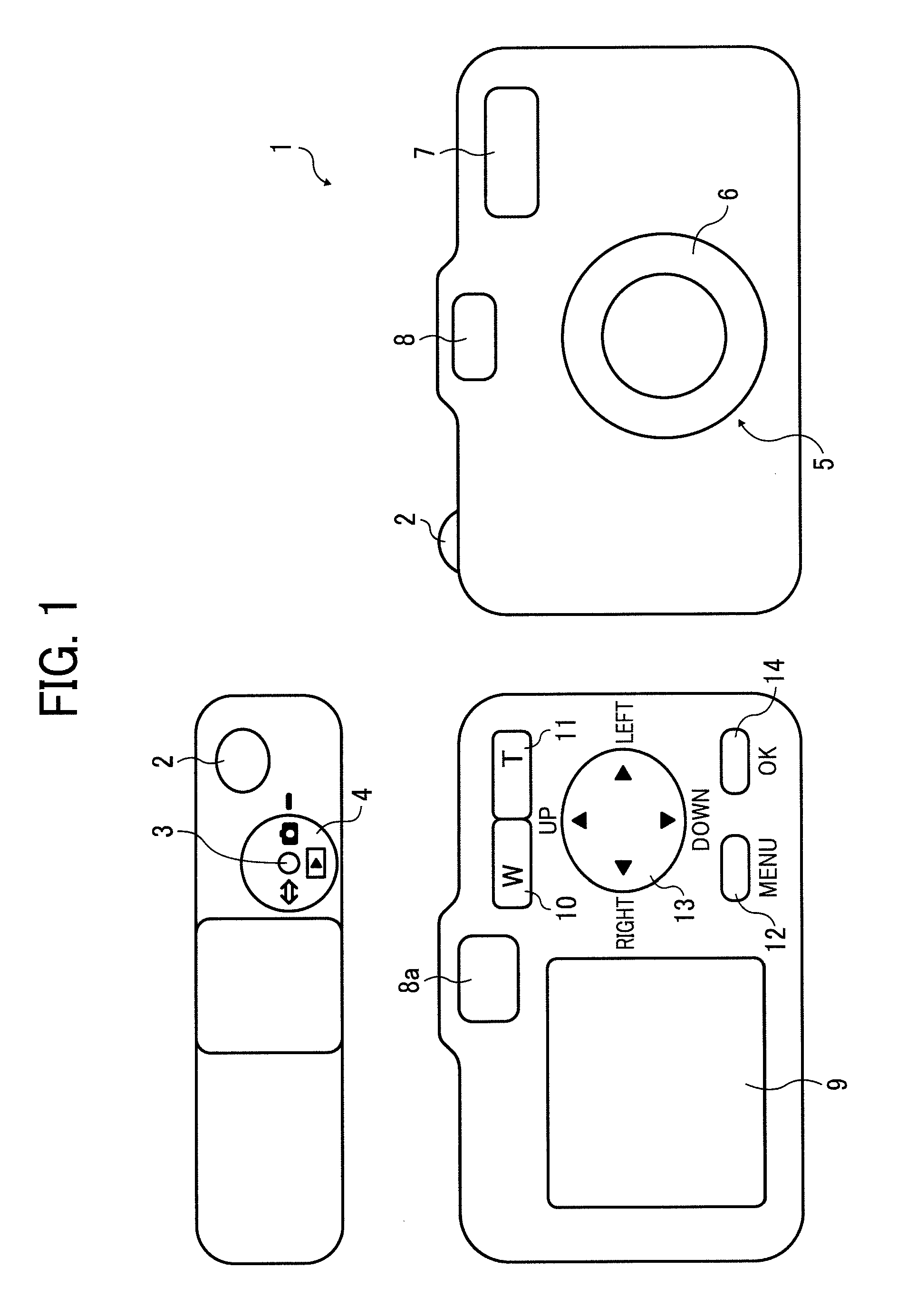
[0048]FIG. 1 schematically shows the exterior of a digital camera as an imaging device of a first embodiment of the present invention. In FIG. 1 a digital camera 1 comprises a shutter button 2, a power-on button 3, and a shooting / reproduction switch dial 4 on a top face as well as a lens barrel 6 having a lens system 5, a strobe light emitting portion 7, and a viewfinder 8 on a front face.
[0049]The digital camera 1 comprises an LCD monitor 9, an eyepiece 8a of the viewfinder 8, a wide-angle zoom switch 10, a telephoto zoom switch 11, a menu button 12, a scene switch button 13, an OK button 14 and the like on a back face. It further comprises, on a side face, a memory card container into which a memory card 15 storing captured image data is inserted.
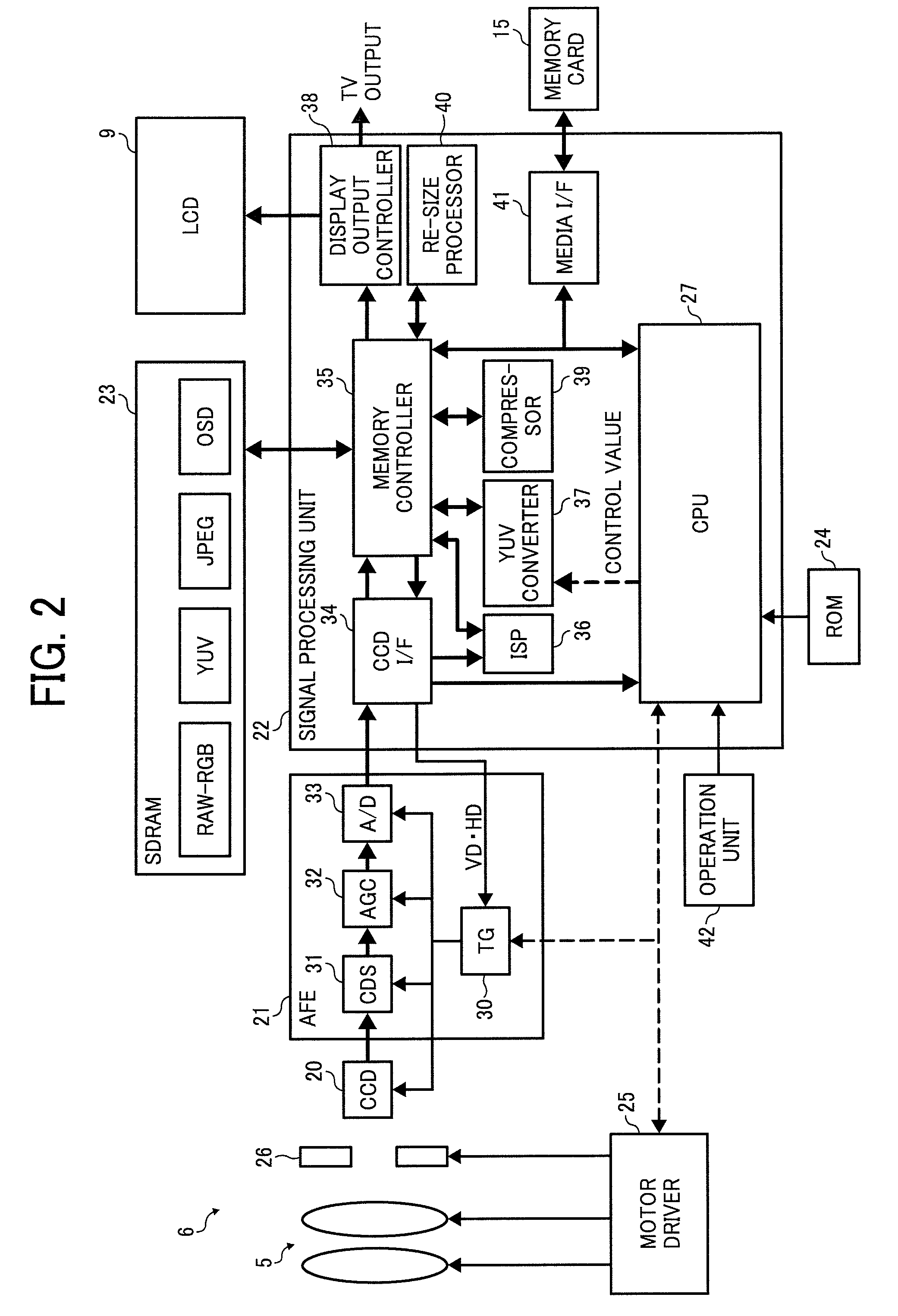
[0050]FIG. 2 shows a structure of the digital camera 1. The digital camera 1 therein contains a CCD 20 as a solid image sensor which forms, on its receiving face, a subject image having passed through the lens system 5 of the lens barrel ...
second embodiment
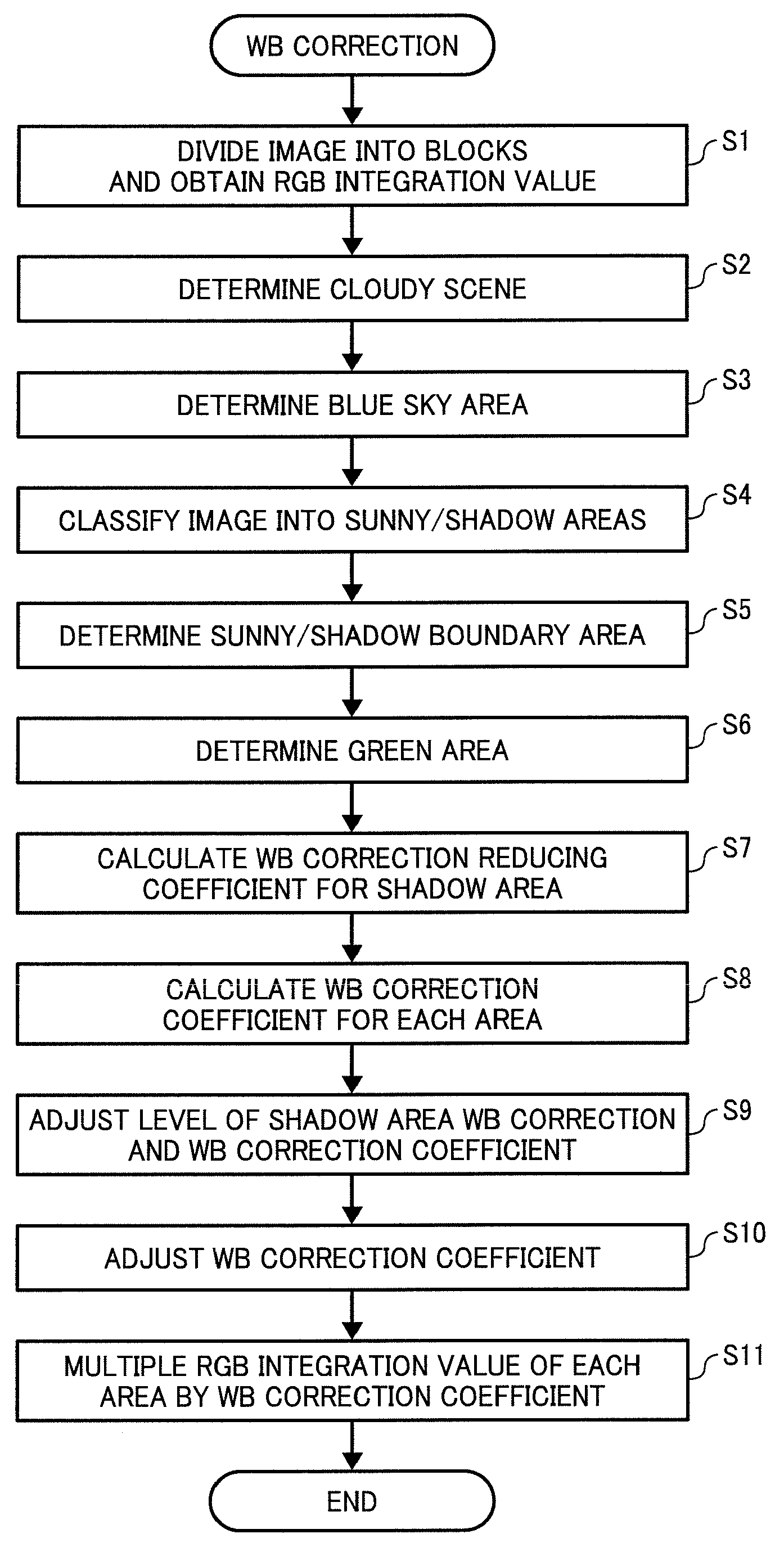
[0122]Now, WB correction of the imaging device according to a second embodiment of the present invention will be described in detail with reference to a flowchart in FIG. 19.
[0123]First, in step S1A, RAW-RGB data are stored in the CCD I / F 34 and a RGB integration value for each of the 256 equally divided blocks 100 is acquired. Note that the number of divided blocks can be arbitrary and the shape of the blocks and the ratio of the blocks to the entire image can be set arbitrarily.
[0124]In step S2A, brightness is calculated from the RGB integration value and the divided blocks 100 are classified into the sunny area and the shadow area based on the brightness and color information, as in step S4 of the first embodiment. In the present embodiment the step 2A is to divide an image into a plurality of areas, the sunny area and the shadow area based on brightness information and color information. The classification of the image into the sunny area and the shadow area is realized by any k...
third embodiment
[0132]Now, WB correction of the imaging device according to a third embodiment of the present invention will be described in detail with reference to a flowchart in FIG. 20. Note that steps in the present embodiment are the same as steps S1A to S5A of the second embodiment, therefore, a description thereof will be omitted. A difference between the second and third embodiments is in that a new step S4B-2 is added between S4 and S5. The step S4B-2 is described in detail in the following.
[0133]The step S4B-2 is an operation performed when a person's face is detected in a captured image by a known face detection technique (a description omitted). In a case where a facial area includes the sunny area and the shadow area in step S2B, the WB correction coefficients for the sunny area and / or shadow area in the facial area are adjusted so that differences in the coefficients therebetween are to be within a second predetermined range R2 after the adjustment in step S4B-1.
[0134]Values of the r...
PUM
 Abstract
Description
Claims
Application Information
 - R&D
- Intellectual Property
- Life Sciences
- Materials
- Tech Scout
- Unparalleled Data Quality
- Higher Quality Content
- 60% Fewer Hallucinations
Browse by: Latest US Patents, China's latest patents, Technical Efficacy Thesaurus, Application Domain, Technology Topic, Popular Technical Reports.
© 2025 PatSnap. All rights reserved.Legal|Privacy policy|Modern Slavery Act Transparency Statement|Sitemap|About US| Contact US: help@patsnap.com


