Structure of an optical path for laser range finding

a technology of optical path and optical path, applied in surveying, distance measurement, instruments, etc., can solve the problems of high mechanical stress, increase the weight and volume of devices, delay generation, and high mechanical stress, and achieve the effect of improving the structure of optical paths

Inactive Publication Date: 2014-09-16
LI NEN TSUA
View PDF3 Cites 3 Cited by
  • Summary
  • Abstract
  • Description
  • Claims
  • Application Information

AI Technical Summary

Benefits of technology

[0008]The main objective of the present invention is to provide an improved structure of an optical path for laser range finding.

Problems solved by technology

All components and connection line contribute to the signal delays in the system.
The greatest delay generates shortly after the system is switched on due to the self-heating of the components.
However, during the repeatedly mechanical switching, the measurement process results in high mechanical stresses and the moving part is worn easily so as to lead an inaccurate measurement result.
Furthermore, complicated designs also increase the manufacturing cost, the device weight and volume.
However, the APD component is a high cost device in the laser distance system, which will increase the total cost.
Furthermore, any change of element or transmit line cause the delay, so does the variation measurement value.
Even more, when the operating temperature of the AVD is varied, the APD cannot work normally so as to lead an inaccurate measurement result finally.

Method used


Image

  • Structure of an optical path for laser range finding
  • Structure of an optical path for laser range finding
  • Structure of an optical path for laser range finding

Examples


Embodiment Construction

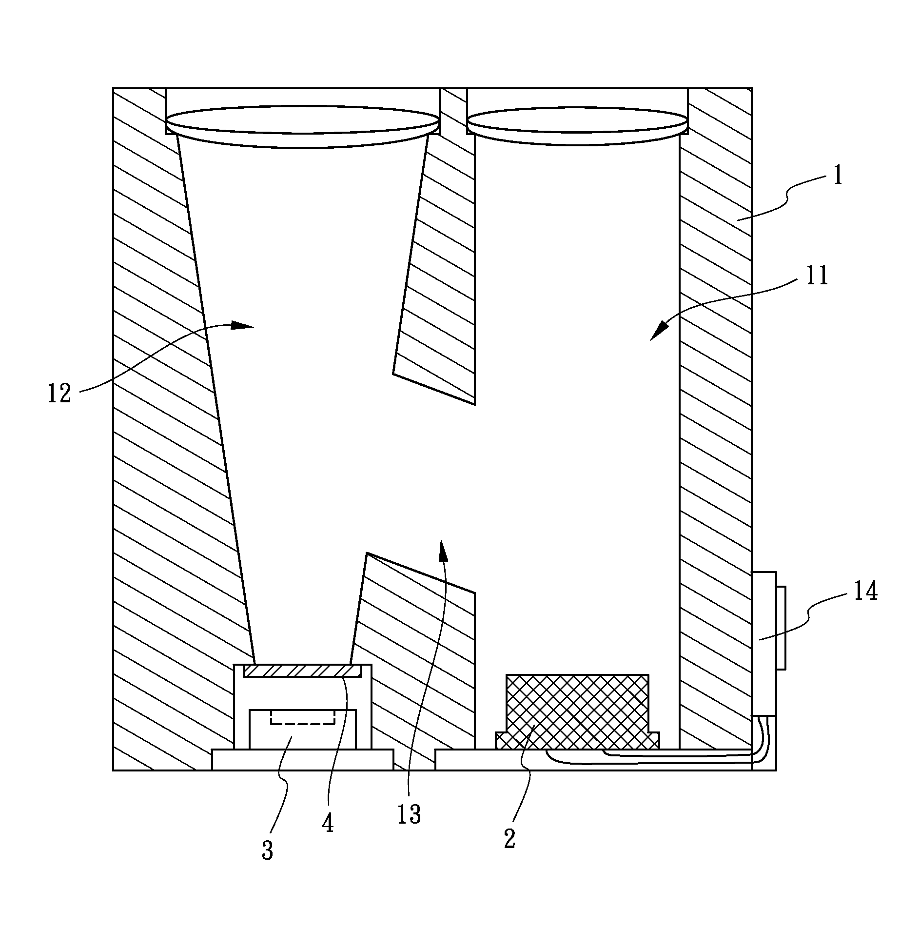
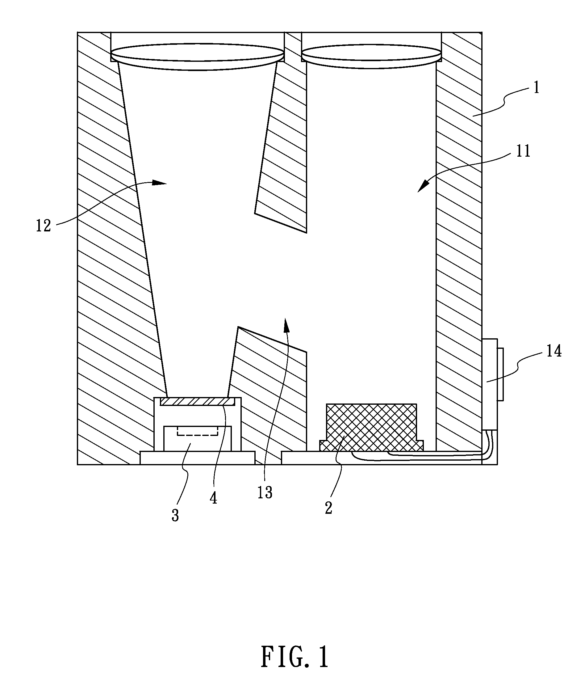
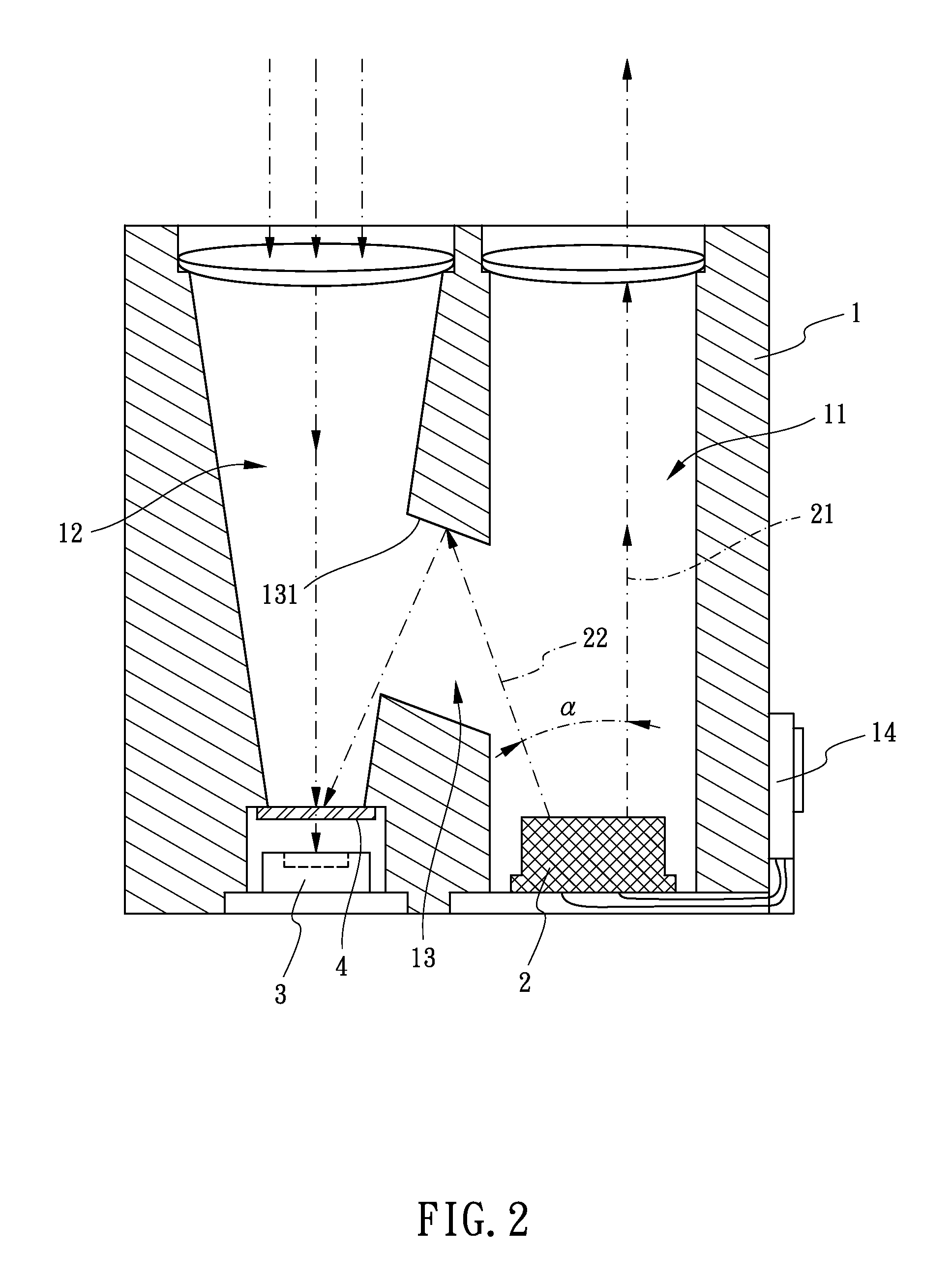
[0023]FIGS. 1-2 show a first embodiment of a structure of an optical path for laser range finding in accordance with the present invention. The structure of an optical path for laser range finding comprises a main body 1 and a light-emitting unit 2 which is assembled in the main body 1.

[0024]The main body 1 has a transmitting channel 11, a receiving channel 12 and a calibration channel 13 defined therein. The calibration channel 13 communicates with the transmitting channel 11 and the receiving channel 12. The calibration channel 13 has a reflecting portion 131 defined at one end thereof. The reflecting portion 131 corresponds to the receiving channel 12. The transmitting channel 11 and the receiving channel 12 are opened through the main body 1 and are parallel with each other.

[0025]The light-emitting unit 2 is assembled in the transmitting channel 11. The light-emitting unit 2 emits two light beams, one light beam is an external optical beam 21 and another light beam is an interna...


PUM


Abstract

A structure of an optical path for laser range finding includes a main body and a light-emitting unit assembled in the main body. The main body has a transmitting channel, a receiving channel and a calibration channel. The light-emitting unit is assembled in the transmitting channel. The light-emitting unit emits an external optical beam and an internal optical beam. The external optical beam is emitted through the transmitting channel. The internal optical beam is emitted to the receiving channel via the calibration channel. An included angle is defined between the external optical beam and the internal optical beam. A receiver is mounted in the receiving channel. Under this arrangement, the external optical beam and the internal optical beam do not interfere with each other.

Description

BACKGROUND OF THE INVENTION1. Field of the Invention[0001]The present invention relates to a structure of an optical path, and more particularly to a structure of an optical path for laser range finding.2. Description of Related Art[0002]A laser rangefinder is a device which uses a laser beam to determine the distance to an object. The basic principle of said laser rangefinder is measuring the phase difference between the transmitted laser and the received APD (avalanche photo diode) is used as conventional laser receiver so that the distance can be calculated.[0003]A conventional device for distance measurement has a mechanical switcher used to obtain an internal reference distance. As a result of mechanical switching of a transmit laser beam, a reference beam and a measuring beam are reached to a receiver alternately, so that the measuring beam and the reference beam are detected in succession manner. During the measuring process, the condition of electric components is changed. A...

Claims


Application Information

Patent Timeline
Patent Type & Authority Patents(United States)
IPC IPC(8): G01C3/08
CPCG01C3/08G01S7/4813G01S7/497G01S17/02
Inventor LI, NEN-TSUA
Owner LI NEN TSUA
Why Eureka
Try Eureka