Transillumination device for a microscope

a technology of a microscope and a slit is applied in the field of slit transillumination devices, which can solve the problems of unsatisfactory slit rectangular shape, insufficient illumination with diffuse light, and inability to depict the relevant details, etc., and achieves the effects of convenient manufacture, simple operation, and convenient manufacturing

Active Publication Date: 2014-09-16
LEICA MICROSYSTEMS (SCHWEIZ) AG
View PDF24 Cites 5 Cited by
  • Summary
  • Abstract
  • Description
  • Claims
  • Application Information

AI Technical Summary

Benefits of technology

[0010]The invention combines the flat conformation of a flat panel light source with the specific configuration of a diaphragm arrangement arranged thereabove, in order to make available a flat, physically compact transillumination base that reproducibly offers a plurality of different illumination types and illumination angles simultaneously with simple operability. The diaphragm arrangement comprises two diaphragm elements movable relative to one another, in particular along a first movement direction, at least one of which has a cutout in order to define a diaphragm opening. The diaphragm opening can be characterized by its respective dimension in two mutually perpendicular directions. The light of the flat panel light source located below passes through the diaphragm opening and illuminates a sample arranged thereabove in the microscope beam path.
[0011]According to a particularly preferred embodiment of the invention, the at least one cutout is shaped so that upon a modification of the relative position of the diaphragm elements with respect to one another along the first movement direction, the dimension of the diaphragm opening is modified more greatly in the first movement direction than in the direction perpendicular thereto. If the movement direction is to be defined hereinafter (without limitation) as a “N-S” (“North-South”) direction, then a relative movement in the N-S direction causes a greater modification of the N-S dimension of the diaphragm opening than of the E-W (“East-West”) dimension. It has been shown that a cutout shape that is axially symmetrical with respect to the movement direction is suitable for reaching this goal, and is also easy to manufacture. The at least one cutout is preferably at least locally concave, circular, parabolic, and / or hyperbolic. These shapes can be manufactured particularly easily.
[0012]The differing dimensional modifications make it possible, in particular, to take into account the two-channel beam geometry of stereomicroscopes in the transillumination device having an integrated flat panel light source. The flat panel light source is located just below the sample plane but not in it, so that the two observation beams of the stereomicroscope, which are located on one another in the sample, then diverge again and are located more or less alongside one another on the flat panel light source. Vignetting-free illumination can be provided by way of a corresponding geometry of the diaphragm opening, in particular an envelope of the adjacently located beam diameters of the two stereo channels, although (in particularly advantageous fashion) only the opening necessary for vignetting-free illumination of the field of view or of the observable portion of the object can be uncovered, and contrast-reducing flare is thereby reduced.
[0013]Advantageously, the two diaphragm elements are embodied as flexible diaphragm curtains. These diaphragm curtains are notable for the fact that they are thin, made of a flexible material, and extend in planar fashion over the flat panel light source. This embodiment is particularly space-saving because flexible diaphragm curtains can be guided relatively freely. It is advantageous in particular to roll up the diaphragm curtains or to guide them through laterally past the flat panel light source and then under the flat panel light source. A further possibility is also to embody the two diaphragm elements as rigid diaphragm plates that are displaceable relative to one another. This yields robust, less-sensitive diaphragm elements.
[0014]Flexible but also rigid diaphragm elements can be moved particularly advantageously by means of diaphragm element shafts. For example, the diaphragm elements can be rolled onto them and unrolled from them. This configuration is particularly compact and relatively stable. The diaphragm opening can be adjusted and / or positioned particularly simply and, in particular, reproducibly by shifting the diaphragm element shafts into specific angular positions.
[0015]Flat panel light sources particularly preferred for the invention are described in the applications DE 10 2011 003 568.0 (corresponding to U.S. application Ser. No. 13 / 359,165 and DE 10 2011 003 569.9 (corresponding to U.S. application Ser. No. 13 / 359,193 of the same date, the entire disclosures of which are incorporated herein by reference. A flat panel light source of this kind comprises a plate-shaped light guide having a lower boundary surface, an upper boundary surface, and at least one lateral surface, as well as at least one light-emitting means which is arranged so that it radiates light from at least two different directions via at least one lateral surface, serving as a light entrance surface, into the light guide in such a way that the light propagates in the light guide as a result of total reflection. In the case of a light guide shaped like a prism or a truncated pyramid, for example, i.e. a light guide having a polygonal base surface, incoupling occurs at at least two of the lateral surfaces. In the case of a cylindrical or frustoconical light guide, i.e. a light guide having an elliptical base surface, incoupling occurs at at least two locations on the enveloping surface that are preferably distributed evenly over the circumference. Incoupling from the side moreover allows a low overall height. Total reflection is disrupted in defined fashion by an element abutting against a contact surface at the lower boundary surface, facing away from the sample, of the light guide, so that the light incident upon the contact surface is for the most part deflected upward, and outcoupling of light occurs on the upper boundary surface of the light guide. The planar area of the contact surface is smaller than the planar area of the lower boundary surface. The element that disrupts total reflection can bring about diffuse scattering or directed reflection of the light propagating in the light guide.
[0016]The use of other flat panel light sources is likewise possible, in particular those constructed on the basis of OLEDs.
[0017]Usefully, a dark-field illumination device is additionally arranged behind the diaphragm arrangement in the emission direction toward the sample, A dark-field illumination can thus also be generated in addition to oblique and bright-field illumination. The arrangement behind the diaphragm arrangement allows the diaphragm opening to be completely closed in the context of dark-field illumination. A light-scattering and / or fluorescing property of the illuminating means (e.g. LEDs) used in bright-field illumination situations is disruptive specifically when the overall height of the illumination device is low, so that in order to achieve high-quality dark-field contrast it is advantageous to cover these illuminating means even when they are switched off.
[0018]A preferred embodiment of the transillumination device possesses a controller and at least one drive system, for example a stepping motor, in order to bring about the relative movement of the diaphragm elements. The controller can in this case be set up so that specific diaphragm positions are preassigned (stored) and can be retrieved and, usefully, also saved by the user. Motorized operation simplifies handling and results in reproducible illumination methods.
[0019]An operating means connected to the controller is preferably provided, the controller being set up to shift the diaphragm elements into a specific relative position upon an actuation of the operating means. These relative positions can be ones predetermined upon manufacture and / or by the user during operation. The user is preferably given the capability for influencing the illumination settings. By modifying setting parameters (e.g. using one or more rotary knobs to apply control to the at least one drive system), it is possible to select a specific diaphragm setting (e.g. a diaphragm trims off two-thirds of the diameter of the pupil). This can then be stored in the controller, and is available for later retrieval.
[0020]Usefully, the controller is set up to shift the diaphragm elements into a specific relative position as a function of a microscope parameter, for example a magnification set on the microscope. The axial position of the pupils of a zoom microscope is generally not fixed. Depending on the magnification, the conjugated plane of the objective pupil migrates from the plane of the diaphragm elements (high magnification) to large distances below the plane of the flat panel light source (low magnification). If the conjugated plane of the objective pupil is located in the plane of the diaphragm elements, uniform pupil manipulation over the object field can be implemented. The greater the distance of the objective pupil from the diaphragm plane, the more pronounced the effect of a manipulation of the object field (vignetting). Depending on the pupil position, which is determined by the zoom setting and objective, suitable diaphragm settings are stored in the controller in order to avoid excessive vignetting. Alternatively or additionally, the diaphragm opening is preferably also adapted in the context of a change in an iris diaphragm setting and / or an objective setting, thus dynamically tracking the optical configuration of the microscope.
[0021]Further advantages and embodiments of the invention are evident from the description and the appended drawings.
[0022]It is understood that the features recited above and those yet to be explained below can be used not only in the respective combination indicated, but also in other combinations or in isolation, without leaving the context of the present invention.

Problems solved by technology

In particular for viewing low-contrast specimens, illumination with diffuse light is not sufficient to depict the relevant details.
The rectangular shape of the slit is, however, not ideal for the circumstances in a stereomicroscope having the two observation channels at an angle to one another.

Method used


Image

  • Transillumination device for a microscope
  • Transillumination device for a microscope
  • Transillumination device for a microscope

Examples


Embodiment Construction

[0040]In the Figures, identical elements are labeled with identical reference characters and, for the sake of clarity, are not explained more than once.

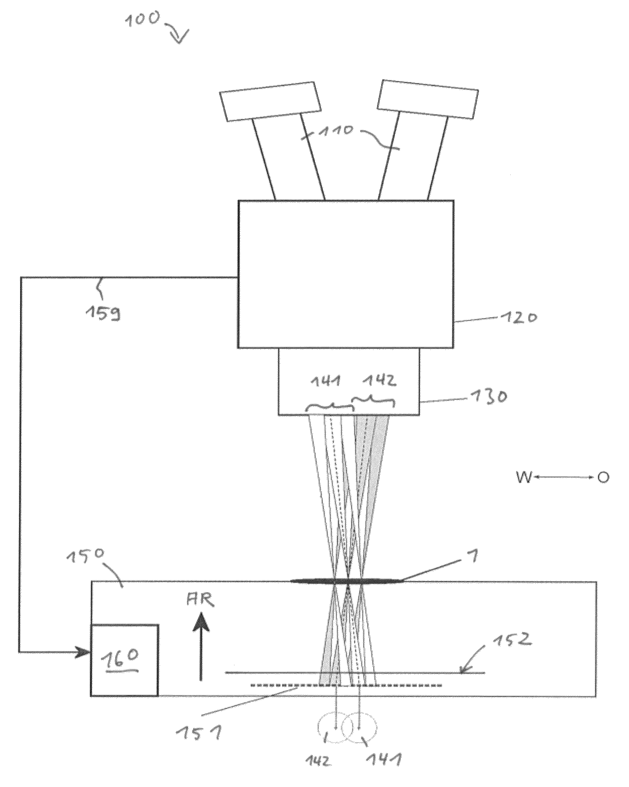
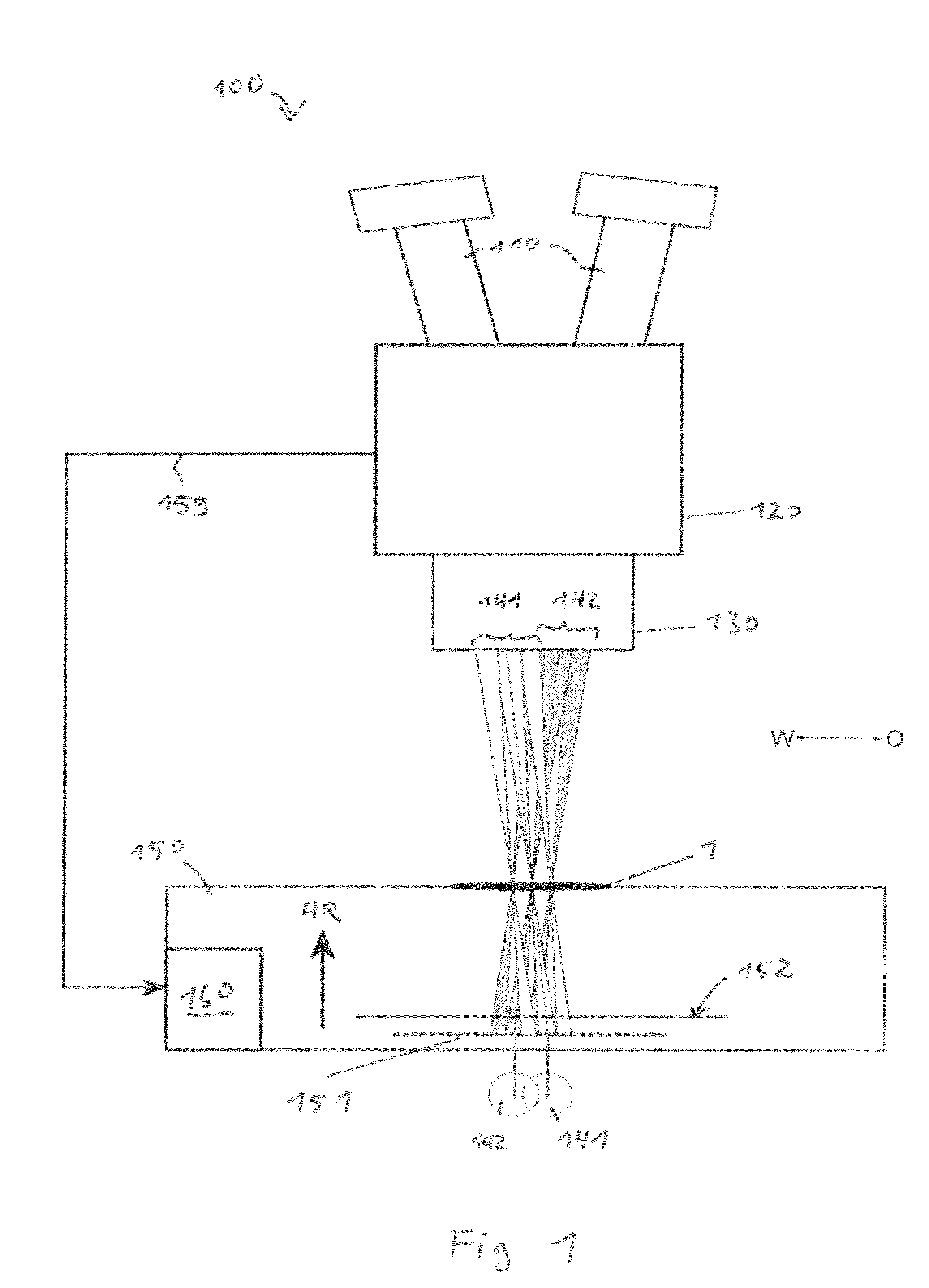
[0041]FIG. 1 schematically depicts, in a sectioned view, a preferred embodiment of a microscope embodied here as stereomicroscope 100. Microscope 100 is equipped with a preferred embodiment of a transillumination device 150 according to the present invention. The microscope is used for examination of an object or sample 1.

[0042]Microscope 100 encompasses two eyepieces 110 that are arranged down-stream from a zoom system 120. Object 1 is viewed through an objective 130. Exemplifying beam paths 141, 142 for the two stereo channels (i.e. for the left and the right eye) are depicted proceeding from objective 130 to sample 1 and on into transillumination device 150. The left channel is labeled 141, and the right channel 142. In the drawing, the observation channels are located next to one another in a W-E direction in the drawing plane. T...


PUM


Abstract

A transillumination device (150) for a microscope (100) comprises a flat panel light source (151), a diaphragm arrangement (152) arranged behind the flat panel light source (151) in the radiating direction (AR) that comprises two diaphragm elements movable relative to one another, at least one of the two diaphragm elements having a cutout, the two diaphragm elements defining, together with the at least one cutout, a diaphragm opening, wherein the dimensions of the diaphragm opening in two mutually perpendicular directions are determined by the position of the diaphragm elements relative to one another.

Description

CROSS REFERENCE TO RELATED APPLICATIONS[0001]This application claims priority of German patent application number 10 2011 003 603.2 filed Feb. 3, 2011, the entire disclosure of which is incorporated by reference herein.FIELD OF THE INVENTION[0002]The present invention relates to a transillumination device (so-called “transmitted-light base”) having an integrated flat panel light source, for microscopes, in particular for those having a continuously modifiable magnification, called “zoom microscopes” for short, in particular stereomicroscopes or macroscopes; and to a microscope having a transillumination device of this kindBACKGROUND OF THE INVENTION[0003]A variety of transillumination devices having an integrated flat panel light source are known in the existing art. These are used for bright-field, dark-field and / or oblique illumination types.[0004]JP 2003-75725 A shows a combined transmitted bright-field and transmitted dark-field illumination device in which it is possible to swi...

Claims


Application Information

Patent Timeline
Patent Type & Authority Patents(United States)
IPC IPC(8): G02B21/06G02B26/02G02B21/02G02B21/08G02B21/12G02B21/22
CPCG02B21/086G02B21/025G02B21/22G02B21/125G02B26/02
Inventor PAULUS, ROBERTSCHNITZLER, HARALDHENRY, DIDIER
Owner LEICA MICROSYSTEMS (SCHWEIZ) AG
Why Eureka
Try Eureka