Placement and area adjustment for hierarchical groups in printed circuit board design

a hierarchical group and printed circuit board technology, applied in computer aided design, program control, instruments, etc., can solve the problems of inefficiency in the placement process, tedious and time-consuming process of placing components in layout design,

Active Publication Date: 2014-09-16
SIEMENS PROD LIFECYCLE MANAGEMENT SOFTWARE INC
View PDF6 Cites 8 Cited by
  • Summary
  • Abstract
  • Description
  • Claims
  • Application Information

AI Technical Summary

Problems solved by technology

As those of ordinary skill in the art will appreciate, due to the large number of components in modern electronic designs, placing components in the layout design can be a tedious and time consuming process.
Although using an HGP methodology to place components within a layout is more efficient than manually placing each component, there are still inefficiencies in the placement process.

Method used


Image

  • Placement and area adjustment for hierarchical groups in printed circuit board design
  • Placement and area adjustment for hierarchical groups in printed circuit board design
  • Placement and area adjustment for hierarchical groups in printed circuit board design

Examples


Embodiment Construction

[0027]The operations of the disclosed implementations may be described herein in a particular sequential order. However, it should be understood that this manner of description encompasses rearrangements, unless a particular ordering is required by specific language set forth below. For example, operations described sequentially may in some cases be rearranged or performed concurrently. Moreover, for the sake of simplicity, the illustrated flow charts and block diagrams typically do not show the various ways in which particular methods can be used in conjunction with other methods.

[0028]It should also be noted that the detailed description sometimes uses terms like “generate” to describe the disclosed implementations. Such terms are often high-level abstractions of the actual operations that are performed. The actual operations that correspond to these terms will often vary depending on the particular implementation.

[0029]Some of the methods described herein can be implemented by so...


PUM


Abstract

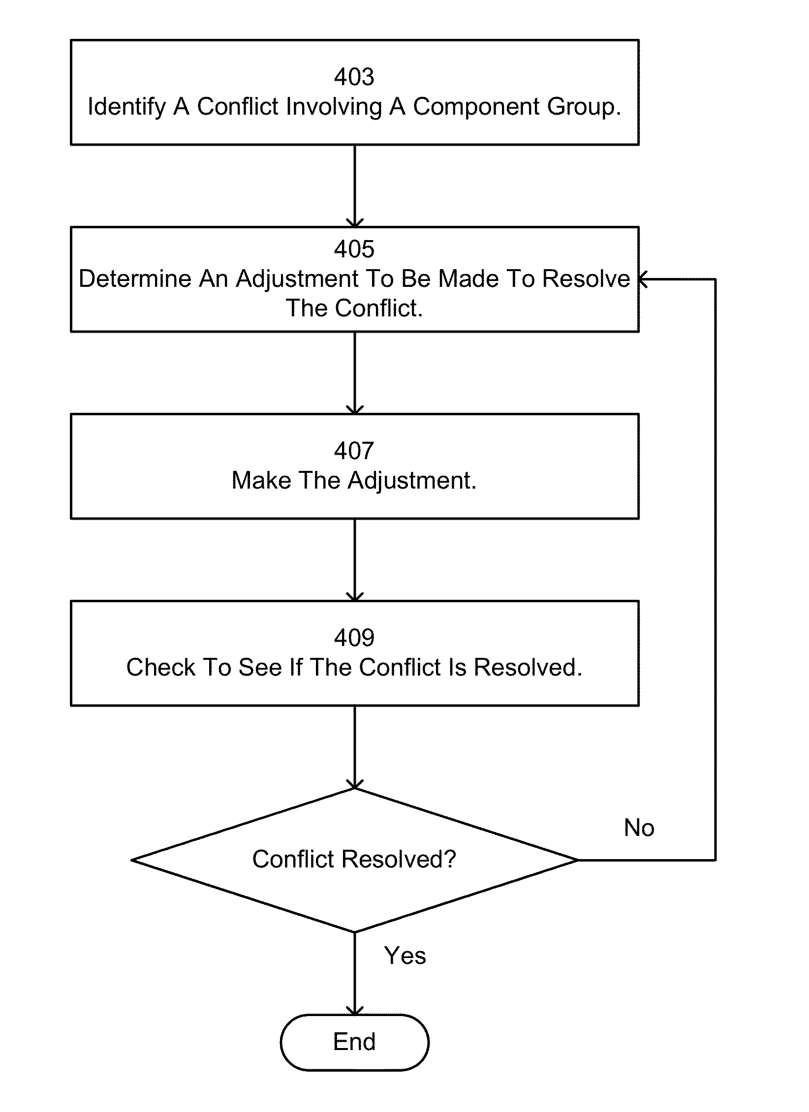
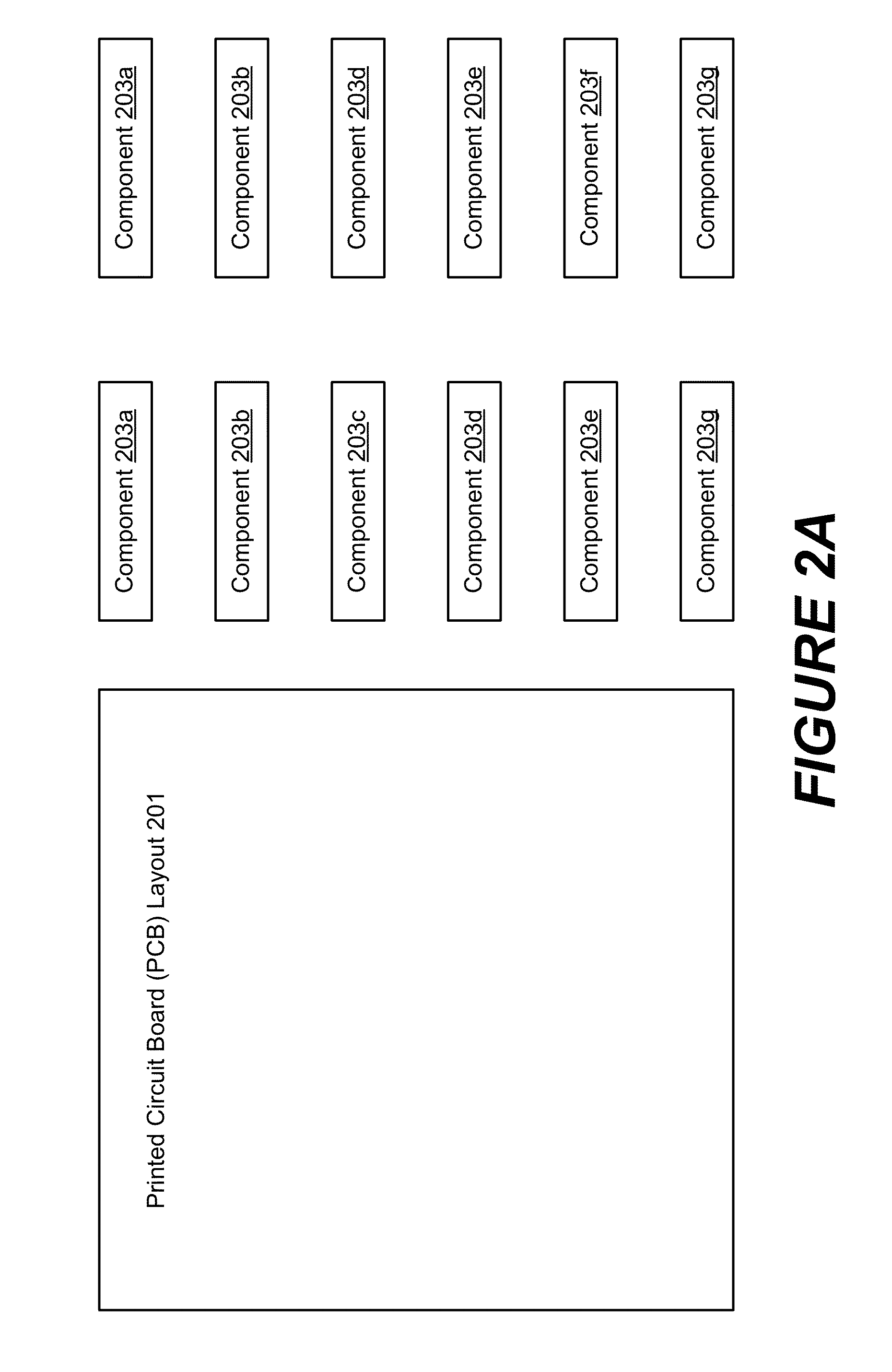
Aspects of the invention are directed towards placing components within a layout design for a PCB. More specifically, various implementations of the invention provide methods and apparatuses that can dynamically adjust the shape or placement of component groups during an HGP process. With some implementations of the invention, an HGP process for planning the layout of a PCB is provided. Furthermore, component groups, which conflict, geographically, with either another component group or some other object within the layout design are allowed to be placed during the planning process. Subsequently, the placement locations for one or both of the conflicting component groups are adjusted to resolve the conflict. In some implementations, the geometric boundary, or footprint, of one or both of the component groups is adjusted to resolve the conflict.

Description

CROSS REFERENCE TO RELATED APPLICATIONS[0001]This application claims priority to a provisional application having the same title, filed Jan. 31, 2012, having first named inventor Gerald Suiter, which was itself originally filed as non-provisional application 13 / 362,664, on Jan. 31, 2012, and subsequently converted to a provisional application via petition (not yet acted upon) dated Sep. 15, 2012. Priority is also claimed from non-provisional application 13 / 362,664, filed Jan. 31, 2012, having the same title, to any extent necessary to perfect priority for this application to Jan. 31, 2012. Each of the referenced applications is herein incorporated by reference in its entirety for all purposes.FIELD OF THE INVENTION[0002]The present invention is directed towards printed circuit board design. More specifically, various implementations provide a circuit board development environment capable of dynamically planning the circuit board layout using a hierarchical group planning process.BAC...

Claims


Application Information

Patent Timeline
Patent Type & Authority Patents(United States)
IPC IPC(8): G06F17/50
CPCG06F17/5081G06F17/5072G06F30/392G06F30/398
Inventor SUITER, GERALD, P.
Owner SIEMENS PROD LIFECYCLE MANAGEMENT SOFTWARE INC
Why Eureka
Try Eureka