
Improved S curve acceleration and deceleration control method based on trigonometric function

A technology of acceleration and deceleration control and trigonometric functions, applied in digital control, program control, electrical program control, etc., can solve problems such as vibration and noise, short time consumption, and system vibration

Active Publication Date: 2018-07-17
SHANDONG UNIV
View PDF5 Cites 32 Cited by
  • Summary
  • Abstract
  • Description
  • Claims
  • Application Information

AI Technical Summary

Problems solved by technology

The linear acceleration and deceleration algorithm is simple and time-consuming, but the acceleration curve is discontinuous, there is a sudden change in speed, and various vibrations and noises are prone to occur, which will cause flexible impact on the movement of CNC equipment. It is suitable for low-speed and low-cost applications that do not require high movement accuracy CNC system
The smoothness of the exponential acceleration and deceleration algorithm is better than that of the linear acceleration and deceleration algorithm, and the motion accuracy is high, but the acceleration and deceleration starting point and end point of the acceleration and deceleration have sudden changes in acceleration and deceleration, and there is also a flexible impact
Trigonometric function acceleration and deceleration mainly uses the sinusoidal curve between 0-π to construct the velocity curve, and then realizes the continuous derivation of acceleration and jerk, so as to achieve the purpose of smooth and smooth transition, but because the current trigonometric function acceleration and deceleration is guaranteed The speed line type cannot give full play to the performance of the jerk and the maximum allowable value of the acceleration of the CNC equipment, causing the speed to fail to reach the expected value in a short time and distance
Some scholars also use trigonometric functions to construct acceleration and jerk curves, and obtain velocity and displacement curves through integrals. There is also the problem that the performance of CNC equipment cannot be fully utilized in order to ensure the line shape of trigonometric functions.
S-shaped curve acceleration and deceleration has the advantages of continuous acceleration curve and smooth speed curve, which is suitable for high-speed and high-precision machining field applications. However, the current S-curve still has a step change in jerk. On the rising and falling edges of the step change, Cause vibration and shock to the feeding system of CNC equipment, affecting the smooth operation
[0004] Chinese patent document (Application No. 201310095677.3) discloses a trigonometric function second-order continuous derivable acceleration and deceleration algorithm for CNC machine tools. Combining the advantages of the general S-shaped acceleration and deceleration curve algorithm, an improved trigonometric function algorithm is proposed, but In this solution, when the jerk is processed, the jerk is directly reduced from the maximum jerk to 0 in the form of a trigonometric function, and there is a large impact from the beginning, and the jerk is not maintained when it reaches the maximum value, the acceleration efficiency is low, and it takes a long time
The trigonometric function has better ability in the continuity of the curve, but it cannot give full play to the performance of the maximum acceleration and jerk of the CNC equipment, and the execution efficiency is low
The S curve has good speed smoothness, but the jerk is discontinuous, which has vibration and impact on the feeding system of CNC equipment.

Method used


Image

  • Improved S curve acceleration and deceleration control method based on trigonometric function
  • Improved S curve acceleration and deceleration control method based on trigonometric function
  • Improved S curve acceleration and deceleration control method based on trigonometric function

Examples


Embodiment 1

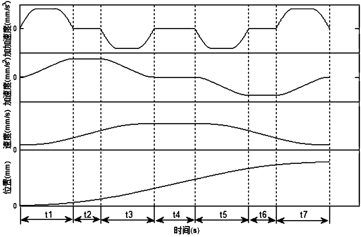
[0185] Such as figure 1 As shown, the improved S-curve acceleration and deceleration control method based on trigonometric functions has a 7-segment structure, namely: acceleration and acceleration section L 1 , Uniform acceleration section L 2 , Decrease acceleration section L 3 , Uniform speed section L 4 , Acceleration and deceleration section L 5 , Uniform deceleration section L 6 And deceleration section L 7 . Corresponding to these 7 movement stages, the total movement time T is also divided into 7 parts, namely the acceleration time t 1 (Set to Δt 1 ), uniform acceleration period time t 2 -t 1 (Set to Δt 2 ), deceleration time t 3 -t 2 (Set to Δt 3 ), uniform speed period time t 4 -t 3 (Set to Δt 4 ), acceleration and deceleration time t 5 -t 4 (Set to Δt 5 ), uniform deceleration period time t 6 -t 5 (Set to Δt 6 ) And deceleration period time t 7 -t 6 (Set to Δt 7 ), where t i (i=1,2...,7) is the moment of the transition point of each stage, Δt i (i=1,2...,7) is the time...

experiment example 1

[0334] Using the control method described in Example 1, programming with C++ and putting in the MATLAB optimization algorithm to obtain the corresponding image.

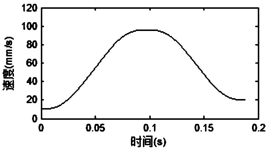
[0335] This experimental example does not include the uniform speed section. The data in Table 2 is set as follows.

[0336] Table 2

[0337] Initial parameters

[0338] After running in MATLAB, the corresponding figure 2 As shown in the table, after the operation is completed, the displacement is set, and the figure 2 It can be seen that the speed of the whole process is smooth.

experiment example 2

[0340] Using the control method described in Example 1, programming with C++ and putting in the MATLAB optimization algorithm to obtain the corresponding image.

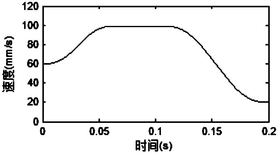
[0341] This experimental example is the case where the uniform acceleration section is not included, and the data in Table 3 is set as follows.

[0342] table 3

[0343] Initial parameters

[0344] After running in MATLAB, the corresponding image 3 As shown in the table, after the operation is completed, the displacement is set, and the image 3 It can be seen that the speed of the whole process is smooth.


PUM


Abstract

The invention relates to an improved S curve acceleration and deceleration control method based on a trigonometric function and belongs to the motion control field. According to the method, a curve isdivided into stages according to different motion characteristics, in the planning process, whether each stage exists is discussed through parameter restriction and actual situations to acquire the operation time of each stage, and a displacement curve after planning is acquired. On the basis of acceleration and deceleration of a traditional S curve, the acceleration and deceleration control method based on the trigonometric function is introduced, acceleration and deceleration continuity can be effectively guaranteed, and impact on numerical control equipment is reduced to the maximum degree.

Description

Technical field: [0001] The invention relates to an improved S-curve acceleration and deceleration control method based on trigonometric functions, belonging to the field of motion control. Background technique: [0002] Acceleration and deceleration control is the key technology in the CNC system. A good acceleration and deceleration control method can effectively avoid the impact, loss of step or vibration during the movement of the CNC equipment, improve the processing accuracy and display quality, and realize the speed of the CNC machine tool. Response, reach the specified speed in a short time, shorten the acceleration and deceleration time, and improve the production efficiency. [0003] At present, the commonly used acceleration and deceleration control methods in CNC systems include: linear acceleration and deceleration, exponential acceleration and deceleration, trigonometric function acceleration and deceleration, and S-shaped acceleration and deceleration. The linear ac...

Claims


Application Information

Patent Timeline
IPC IPC(8): G05B19/416
CPCG05B19/4163G05B2219/35221
Inventor 张承瑞袁佶鹏倪鹤鹏姬帅胡天亮刘亚男
Owner SHANDONG UNIV
Learn More