Vertically adjustable caster wheel apparatus

a caster wheel and vertical adjustment technology, applied in the direction of shock absorbers, furniture parts, manufacturing tools, etc., can solve the problems of not being easily adaptable, large and heavy, and limited overall vertical dimension of the caster wheel, and achieving the effect of reducing and increasing the cost of caster wheel replacemen

Active Publication Date: 2014-09-23
ROSS DESIGN & ENG
View PDF54 Cites 10 Cited by
  • Summary
  • Abstract
  • Description
  • Claims
  • Application Information

AI Technical Summary

Benefits of technology

[0013]The elastic member may have a substantially cylindrical configuration having an aperture extending there through along a longitudinal axis. The first retainer is received by the aperture at one end of the elastic member, and the second retainer is received by the aperture at the opposite end of the elastic member. The first retainer and second retainer are spaced in the aperture of the elastic member when the elastic member is not extensively compressed, and the first and second retainers engage one another in the aperture of the elastic member when the elastic member is extensively compressed. The first and second retainers may each have an annular protuberance extending therefrom, and the first retainer and the second retainer have the annular protuberance press fit into the aperture of the elastic member to prevent the movement of the first retainer and the second retainer relative to the elastic member.

Problems solved by technology

For instance, steel compression or torsional coil springs have been used to bias resiliently supported casters, but such springs are relatively large and heavy and not readily adaptable for many caster wheel installations, wherein the overall vertical dimension available for the caster wheel is limited, and the vertical profile of the caster wheel assembly must be concise.
In addition, such springs are typically expensive, thereby leading to inefficiencies that are undesirable in the caster wheel industry.
Such designs are typically less expensive than the above-noted steel compression or torsional coil springs; however, such polyurethane blocks typically break down after extended use and cycled loads, thereby requiring replacement and / or repair of the caster wheel.
Heavy duty caster wheel assemblies also lack a quick and simple method of vertically adjusting the roller or wheel height of the caster wheel assembly.

Method used


Image

  • Vertically adjustable caster wheel apparatus
  • Vertically adjustable caster wheel apparatus
  • Vertically adjustable caster wheel apparatus

Examples


first embodiment

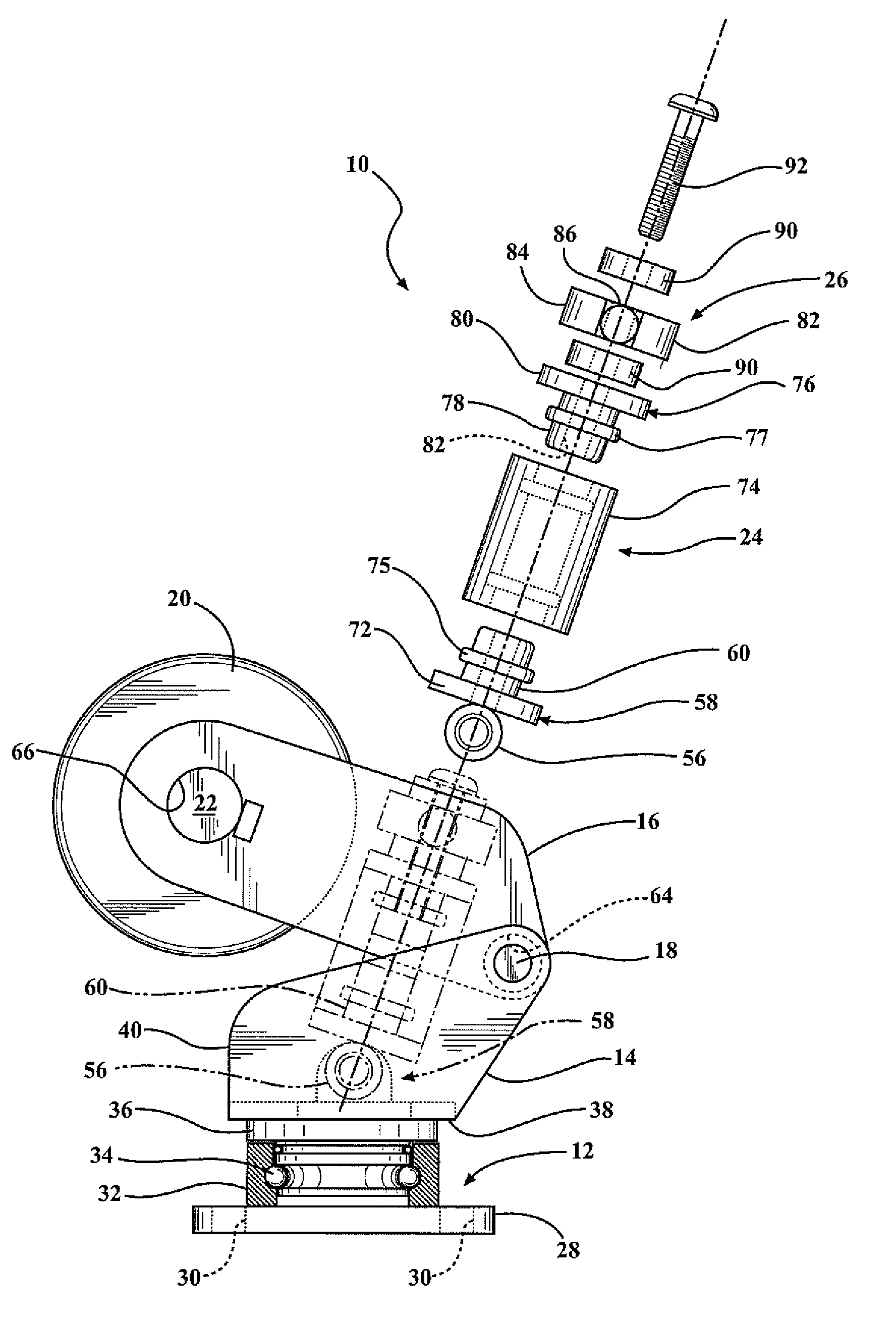
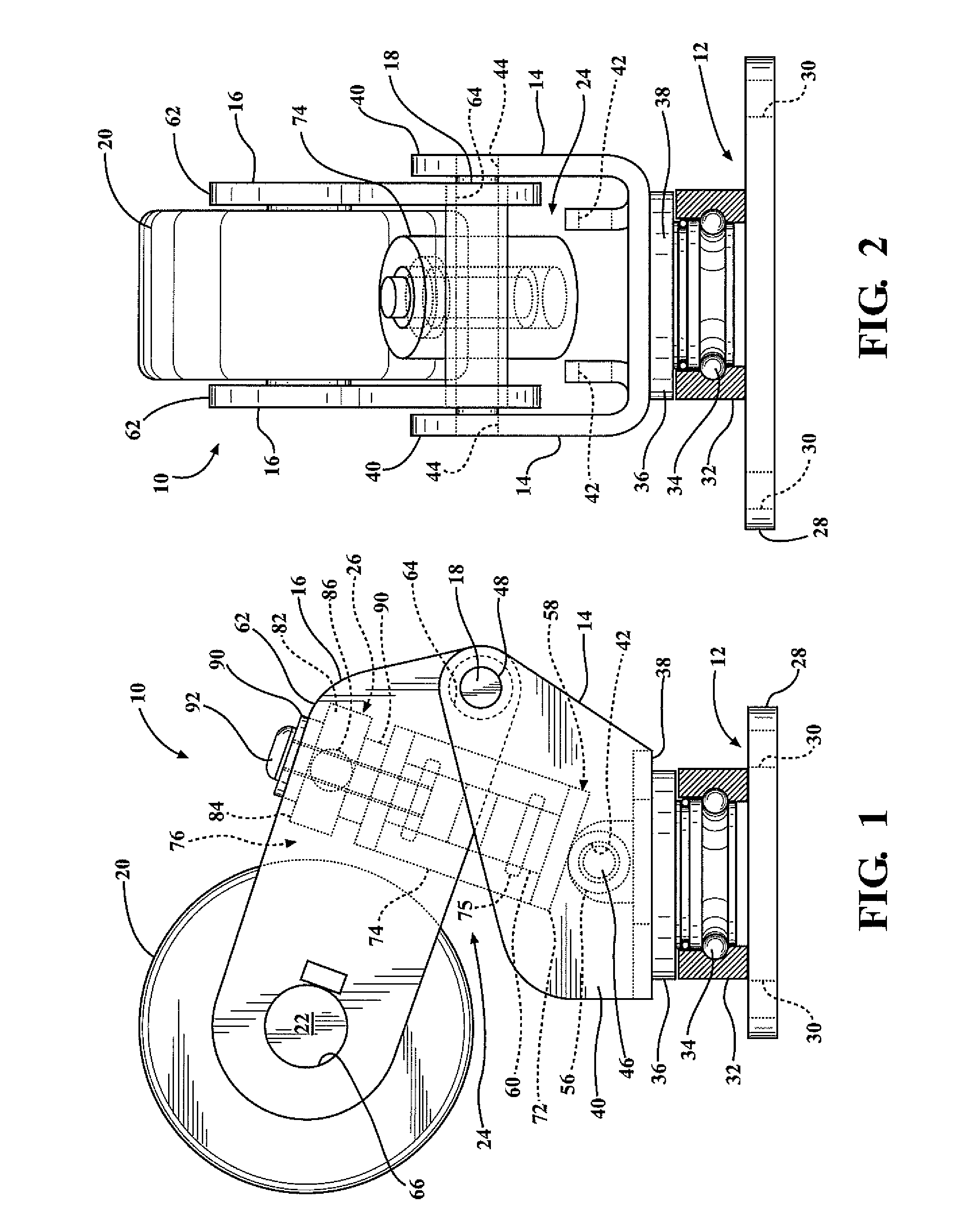
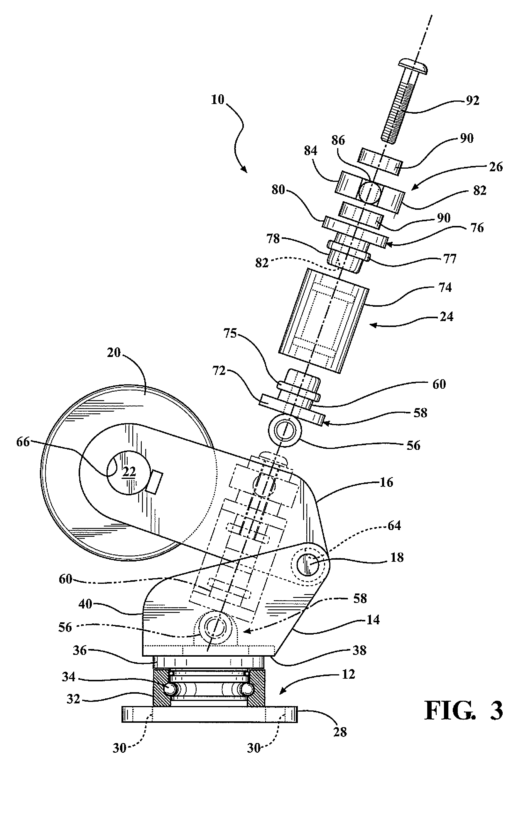
[0032]To provide vertical adjustment of the wheel 20 of the caster wheel apparatus 10, the vertical adjusting means 26 of the caster wheel apparatus 10 is shown in FIGS. 1-3. To connect the elastic assembly 24 to the wheel frame 16, the vertical adjusting means 26 provides a swivel plate 82 having a substantially cylindrical body portion 84 with a threaded aperture extending therethrough. A pair of substantially cylindrical rods 86 extend integrally outward from the cylindrical portion 84 of the swivel plate 82. The rods 86 of the swivel plate 82 are received by a pair of coaxially aligned apertures 88 provided in the plates 62 of the wheel frame 16. Steel washers or spacers 90 may be inserted on one or both sides of the swivel plate 82 and are placed atop the upper retainer 76 of the elastic assembly 24. A threaded fastener or bolt 92 is inserted through the steel washers 90 and threaded through the threaded apertures in the cylindrical portion 84 of the swivel plate 82 and into th...

second embodiment

[0033]The vertical adjusting means 26 may also take on a different structure, as shown in the present invention in FIGS. 4-6. In this embodiment, the vertical adjusting means 26 provides a floating retainer 94 having a substantially U-shaped plate-like configuration with a threaded aperture 96 extending therethrough. A pair of substantially cylindrical rods 98 are integrally connected to and extend outwardly from the floating retainer 94. The rods 98 of the floating retainer 94 are received by the coaxial apertures 88 provided in the plates 62 of the wheel frame 16. This allows the elastic assembly 24 to pivot with respect to the wheel frame 16. A swivel lock nut 100 having a threaded aperture 102 extending therethrough is aligned with and connected to the underside of the floating retainer 94 in the upper retainer 76 of the elastic assembly 24. The swivel lock nut 100 has a similar configuration to that of the upper retainer 76 wherein a substantially cylindrical portion 104 is con...


PUM

PropertyMeasurementUnit
vertical heightaaaaaaaaaa
elasticaaaaaaaaaa
forcesaaaaaaaaaa

Abstract

A vertically-adjustable caster wheel apparatus for use on a forklift truck, material handling cart, and the like. The caster wheel apparatus of the present invention provides a yolk frame having a pivot pin connected to and extending through the yolk frame. A wheel frame has one end pivotally connected to the yolk frame and a second end rotatably connected to a wheel. An elastic member has a first retainer connected to one end of the elastic member and a second retainer connected to an opposite end of the elastic member, wherein the first retainer is connected to the pivot pin in the yolk frame to allow the elastic member to pivot with respect to the yolk frame. Means for adjusting the vertical height of the wheel is provided by adjusting the angle of the wheel frame relative to the yolk frame.

Description

CROSS-REFERENCE TO RELATED APPLICATIONS[0001]This application claims the benefit of U.S. Provisional Patent Application No. 61 / 716,040, which was filed on Oct. 19, 2012, and is incorporated herein by reference in its entirety.FIELD OF THE INVENTION[0002]The present invention relates to the field of adjustable caster wheels, and in particular, a caster wheel having a polyurethane cylinder for absorbing high levels of forces realized by the caster wheel while also providing a vertical adjustment of the caster wheel without having to fully disassemble and reassemble the caster wheel.BACKGROUND OF THE INVENTION[0003]Heavy-duty caster wheels are well-known within the industry, especially the forklift truck industry. Such heavy-duty casters are used to support relatively heavy loads transported by small forklift trucks, material handling carts, and the like. Such heavy-duty caster wheels commonly use various biasing means or elastomeric means to absorb high levels of forces or loads appli...

Claims


Application Information

Patent Timeline
Patent Type & Authority Patents(United States)
IPC IPC(8): A47B91/00B60B33/00B60B33/04B60G17/02B66F9/075F16F1/44
CPCB60B33/045F16F2224/025B66F9/07586B60B2360/324B60B33/0049B60B2900/313B60B33/0039B60B2310/305B60G2202/143F16F2230/0005B62B2301/04B60Y2200/15B60B2360/50B60G2300/022B60B2900/711B60G17/02F16F1/44B60B33/04B60B33/0068B60B2900/351Y10T16/182Y10T16/193Y10T16/212
Inventor PLATE, JACK
Owner ROSS DESIGN & ENG
Why Eureka
Try Eureka