
Apparatus, vehicle, and method for determining a thermostat malfunction in an engine cooling system

a technology of engine cooling system and thermostat malfunction, which is applied in the direction of engine testing, structural/machine measurement, instruments, etc., can solve the problems of false determination, inability to quickly warm up the internal combustion engine, and inability to accurately determine the presence or absence of thermostat malfunction, etc., to achieve accurate detection, increase the cost, and increase the effect of accuracy

Inactive Publication Date: 2014-09-23
TOYOTA JIDOSHA KK
View PDF14 Cites 6 Cited by
  • Summary
  • Abstract
  • Description
  • Claims
  • Application Information

AI Technical Summary

Benefits of technology

The invention is a device and method to determine if a thermostat is working properly. It checks if the temperature of the coolant is below a certain level for a set amount of time. This way, it can accurately detect any malfunctions in the thermostat without being too expensive.

Problems solved by technology

However, in the case where the thermostat becomes abnormal due to fixation or the like, the coolant can sometimes circulates via the radiator even during a warm-up, in which case the internal combustion engine cannot be quickly warmed up.
However, in the case where coolant in a medium passage in a cooling apparatus is circulated by an electric water pump, there is possibility of false determination of the presence or absence of malfunction of the thermostat.
As a result, there is a possibility of false determination when the presence or absence of malfunction of the thermostat is to be determined through the use of the detection value from the sensor.
The water pump of the thermostat malfunction detection apparatus disclosed in the foregoing patent application publication uses the engine as a motive power source, and the aforementioned problems are not considered at all in conjunction with the disclosed construction.

Method used


Image

  • Apparatus, vehicle, and method for determining a thermostat malfunction in an engine cooling system
  • Apparatus, vehicle, and method for determining a thermostat malfunction in an engine cooling system
  • Apparatus, vehicle, and method for determining a thermostat malfunction in an engine cooling system

Examples


Embodiment Construction

[0020]Embodiments of the invention will be described hereinafter with reference to the drawings. In the following description, the same component parts are denoted by the same reference characters. Those component parts are also the same in name and function. Therefore, detailed descriptions thereof will not be repeated.

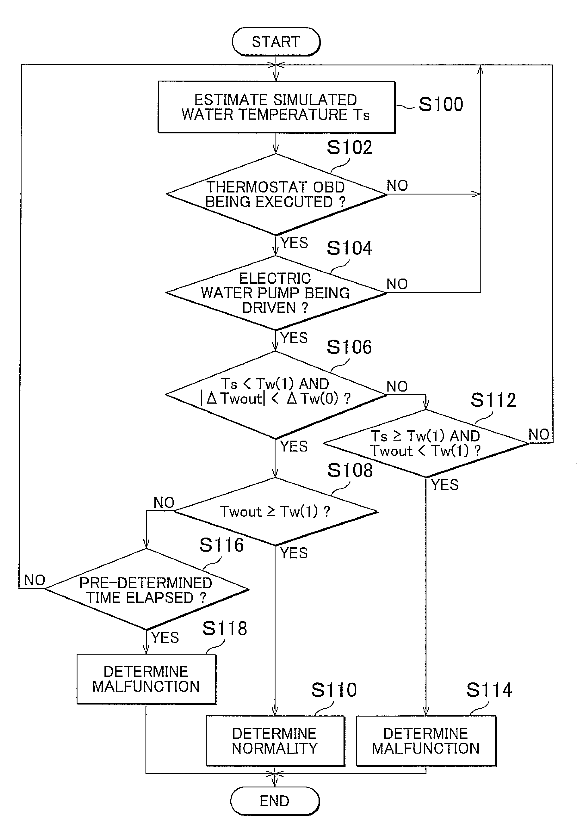
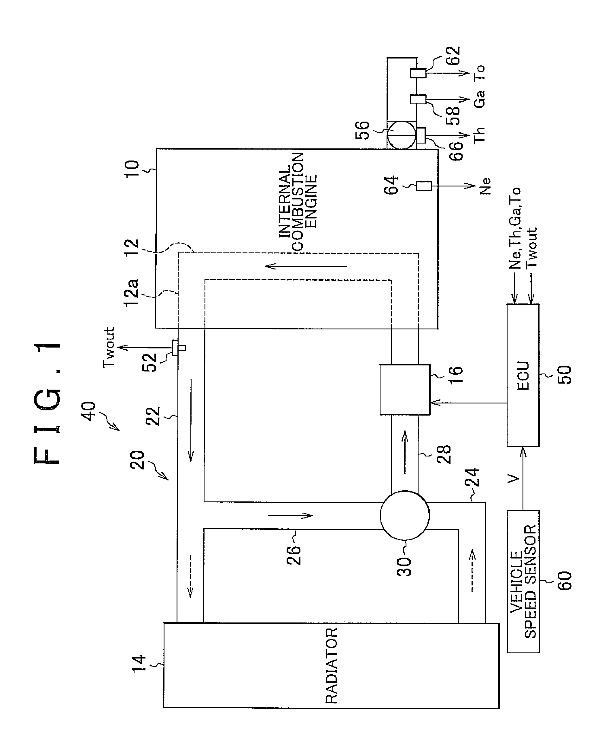
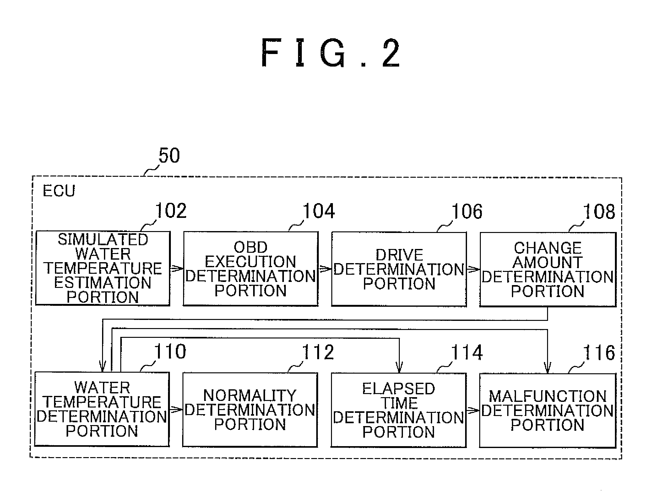
[0021]As shown in FIG. 1, in an embodiment of the invention, a cooling apparatus 40 includes a water jacket 12 formed within an internal combustion engine 10, a radiator 14, a circulation passage 20 for circulating cooling water (coolant) between the radiator 14 and the water jacket 12, a thermostat 30 provided in an intermediate portion of the circulation passage 20, an electric water pump 16 provided in an intermediate portion of the circulation passage 20, and an ECU (Electronic Control Unit) 50. A malfunction determination apparatus in accordance with this embodiment is realized by the ECU 50. In this embodiment, the cooling apparatus 40 and the internal combusti...


PUM


Abstract

A malfunction determination apparatus for a cooling apparatus that cools an internal combustion engine by circulating a coolant through an interior of the internal combustion engine, using an electric pump, after the internal combustion engine is started includes: a detection portion that detects the coolant temperature; and a determination portion that determines a malfunction has occurred in a thermostat, if a state in which the detected coolant temperature remains below a first threshold temperature after the electric pump begins operating, following start of the internal combustion engine, continues for at least a pre-determined time. The thermostat is a thermostat for switching from a first passage for circulating the coolant without passage via an interior of a radiator of the cooling apparatus to a second passage for circulating the coolant via the interior of the radiator, as the coolant temperature rises.

Description

CROSS REFERENCE TO RELATED APPLICATIONS[0001]This application claims priority to Japanese Patent Application No. 2010-228711 filed on Oct. 8, 2010, which is incorporated herein by reference in its entirety including the specification, drawings and abstract.BACKGROUND OF THE INVENTION[0002]1. Field of the Invention[0003]The invention relates to a technology of determining the presence or absence of occurrence of a malfunction of a cooling apparatus of an internal combustion engine. More particularly, the invention relates to a technology of highly accurately determining the presence or absence of occurrence of a malfunction of a thermostat in the case where coolant that passes via an interior of an internal combustion engine is circulated by an electric pump.[0004]2. Description of Related Art[0005]An internal combustion engine is provided with a cooling apparatus that cools component parts that are heated by heat that is produced by combustion. Such a cooling apparatus includes a th...

Claims


Application Information

Patent Timeline
Patent Type & Authority Patents(United States)
IPC IPC(8): G01M15/05G01M15/04
CPCG01M15/042
Inventor NISHIGAKI, TAKAHIRO
Owner TOYOTA JIDOSHA KK
Learn More