Utility metering

a technology for utility meters and meters, applied in the field of utility meters, can solve the problems of inability to connect such meters to permanently-wired appliances, inconvenient information to obtain, and very little idea of how they are actually using energy and where they can cut back, etc., and achieve the effect of less computational intensive and more accura

Inactive Publication Date: 2014-09-23
ISIS INNOVATION LTD
View PDF17 Cites 8 Cited by
  • Summary
  • Abstract
  • Description
  • Claims
  • Application Information

AI Technical Summary

Benefits of technology

[0019]The present invention has the advantage of being less computationally intensive and more accurate than previous metering apparatus and methods.

Problems solved by technology

For example, in the case of electricity supply, the information is presented to the consumer in terms of the number of kilowatt hours of electrical energy that has been used, which is meaningless to many people, and gives very little idea about how they are actually using the energy and where they can cut back.
It is a problem to provide this information.
However, this information is inconvenient to obtain, and for fully monitoring the consumption at a particular site, such as a house, a separate metering device would have to be plugged into every socket to monitor every appliance, and it is generally not possible to connect such metering devices to permanently-wired appliances, such as cookers, which are typically some of the largest consumers of energy.
However, distinguishing between certain types of load can be difficult in some cases.
These dimmer switches present a significant challenge to electricity usage monitoring systems because they transform a load that is nominally resistive and of fixed power, to a continuously variable power load, which additionally has a variable reactive power dependent on the level of dimming.
There is a problem in providing a reliable way of distinguishing such loads and of measuring the power consumed by this class of device.
However, there is the problem of distinguishing between appliances that have very similar characteristics with regard to consumption of electricity, for example appliances that present substantially the same electrical load.
A particular problem is with heating appliances which generally have a resistive heating element which presents a purely resistive load, making it difficult to distinguish between say a toaster and a kettle.
Therefore it may not be possible to separately totalize the power consumed by two 1200 W resistive appliances e.g. a toaster and a quartz space heater.
However, there is the problem of distinguishing between appliances which have very similar characteristics with regard to consumption of the same utility, for example appliances which present substantially the same electrical load.

Method used


Image

  • Utility metering
  • Utility metering
  • Utility metering

Examples


Embodiment Construction

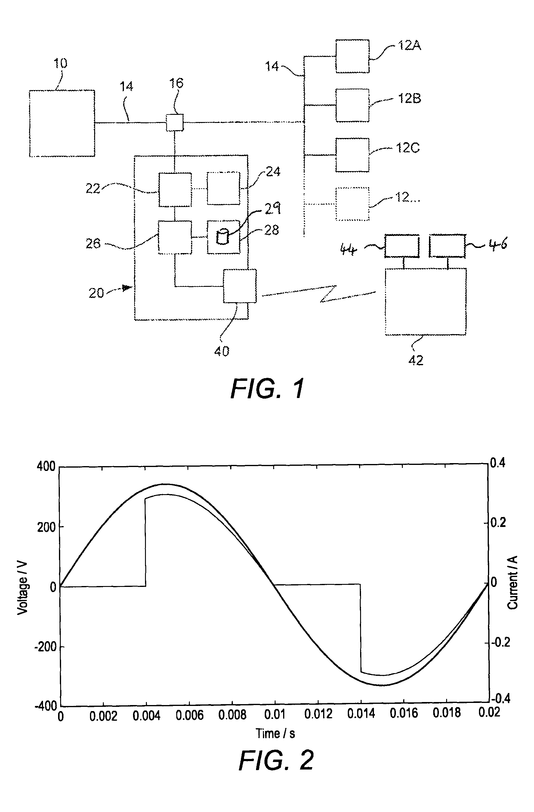
[0042]An apparatus according to a first embodiment of the invention will now be described. FIG. 1 shows the hardware components of a system incorporating the apparatus for metering the use of electricity, or more correctly for metering electrical energy. The apparatus will be referred to simply as the meter.

[0043]In FIG. 1, the electricity supply to the site, for example a house, apartment, office, shop, school and so forth is denoted 10. The electricity is supplied to a plurality of appliances 12A, 12B, 12C, 12 . . . by means of conventional wiring 14. The appliances and wiring are simply shown schematically in FIG. 1, but may, of course, be configured in any appropriate way, such as via a consumer unit with circuit breakers or fuses, and with one or more ring main circuits with branches or spurs. A sensor 16 is provided to measure the total instantaneous current being provided to all of the appliances 12 from the supply 10, and also to measure the instantaneous voltage of the elec...


PUM


Abstract

An apparatus has an input section arranged to receive values representative of the total instantaneous supply of electrical current as a function of time from an alternating voltage supply. Current waveforms comprising sets of values representative of the cyclic waveform of the electric current supply are obtained. A delta waveform generator calculates the difference between a current waveform and an earlier current waveform. An edge detector is arranged to detect an edge or edges in the delta waveform. An analysis section is arranged to identify at least one appliance load based at least on information on the edge or edges detected by the edge detector, and to determine the electrical energy consumed by said appliance load.

Description

FIELD OF THE INVENTION[0001]The present invention concerns an apparatus for metering the use of a utility, such as electricity, gas, oil or water, supplied to one or more appliances. For example, when the utility is electricity, the present invention concerns determining the electrical power consumed by one or more individual appliances among the plurality of appliances, e.g. by detecting a variable power load.BACKGROUND OF THE INVENTION[0002]There is an increasing concern to reduce the consumption of resources, both at a domestic level in residential buildings, and at a commercial level in offices, shops, factories and so forth. The reasons for this are both to save costs and also because of concerns for the environment, such as the conservation of scarce resources, for example water in regions where rainfall is low, to reduce CO2 emissions, and to conserve finite resources such as coal, gas and oil.[0003]Conventionally, consumers receive bills from utility companies that may indic...

Claims


Application Information

Patent Timeline
Patent Type & Authority Patents(United States)
IPC IPC(8): G01R13/00G01R21/06G01R25/00G01R19/00
CPCG01R21/1331Y02B90/2607G01R27/02Y04S40/12G01R21/133G01D4/00Y04S20/30G01D2204/24
Inventor DONALDSON, JAMESMCCULLOCH, MALCOLM
Owner ISIS INNOVATION LTD
Why Eureka
Try Eureka