Electric tool

a technology of electric tools and battery packs, applied in the direction of electric controllers, dynamo-electric converter control, instruments, etc., can solve the problems of inability to meet user's demand, motors may break easily, user may feel uncomfortable, etc., to increase the scope of available battery packs, improve convenience, and ensure safety

Active Publication Date: 2014-09-30
PANASONIC CORP
View PDF30 Cites 31 Cited by
  • Summary
  • Abstract
  • Description
  • Claims
  • Application Information

AI Technical Summary

Benefits of technology

[0007]It is an object of the present invention to provide an electric tool, which can improve the convenience through increase in the scope of available battery packs, and can also ensure the safety.
[0009]In this configuration, since said control circuit is configured to control the output of said motor based on identification information for the type of said battery pack that has been connected, provided by said identification means, the electric tool can also use a battery pack that has a higher rated output voltage than a proper matching battery pack. Furthermore, the electric tool can avoid the probability that the temperature of said motor rises above an acceptable value through the connection of the battery pack having the higher rated output voltage. Then, because the plurality of battery pack types, having different rated output voltages, can be used, the electric tool can improve the convenience, and can also maintain high safety and endurance.

Problems solved by technology

However, when the proper battery pack has been used up and there is only an upper battery pack around and a user wishes to work using the upper battery pack for only a short time, the electric tool can not meet the user's demand.
However, when the upper battery pack has been connected and used for a long time, the motor may break down easily due to the temperature rise, or the user may feel uncomfortable due to the temperature rise of the tool or may burn his hand with the tool.

Method used


Image

  • Electric tool
  • Electric tool
  • Electric tool

Examples


Embodiment Construction

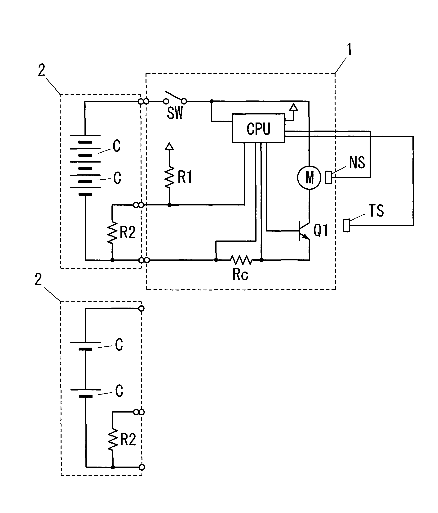
[0026]An embodiment of the present invention will be described below. An electric tool comprises a main unit 1 that has a motor M built-in as a power source, and a removable battery pack 2 as a power supply, and then operates (see FIG. 1). The electric tool further comprises a control circuit CPU that controls the driving of motor M, a switching element Q1 for the driving, a rotating speed sensor NS, and a temperature sensor TS. Temperature sensor TS is located near switching element Q1 and motor M.

[0027]Control circuit CPU obtains rotating speed information from rotating speed sensor NS, and obtains temperature information from temperature sensor TS, and detects a load of motor M from a voltage between both ends of a current sensing resistor Rc, as a load current value. Then, control circuit CPU is configured to detect identification information for the type of battery pack 2 that has been connected, and a battery voltage on-load.

[0028]In regard to battery pack 2, there is a plural...


PUM


Abstract

An electric tool comprises a removable battery pack 2 as a power supply, a motor M as a power source, a drive unit being driven by said motor, a switch SW as an operation input unit, and a control circuit CPU controlling the driving of said motor according to the operation of said switch. The electric tool further comprises a power supply connection unit that enables a plurality of battery pack types, which have different rated output voltages, to be selectively connected, and an identification means that identifies the type of said battery pack that has been connected. Said control circuit is configured to control an output of said motor based on identification information for the type of said battery pack that has been connected, provided by said identification means.

Description

TECHNICAL FIELD[0001]The invention relates generally to electric tools and, more particularly, to an electric tool comprising a removable battery pack as a power supply.BACKGROUND ART[0002]Generally, an electric tool comprises a motor that has an output appropriate for the intended use. Then, when the electric tool comprises a removable battery pack as a power supply, the battery pack has a voltage and a capacity corresponding to the output of the motor. For this reason, when there are several different types of electric tools, it means that there are also several different types of battery packs that have voltages and capacities corresponding to the several different types of electric tools, respectively.[0003]In regard to these several different types of battery packs, Japanese Patent Application Laid-Open No. 2002-027675 discloses an electric tool which is configured to be able to use a battery pack under some conditions with relation to a voltage, even if the battery pack is not...

Claims


Application Information

Patent Timeline
Patent Type & Authority Patents(United States)
IPC IPC(8): H02P1/42B25F5/00H02J7/00
CPCB25F5/00
Inventor MIYAZAKI, HIROSHISHIMIZU, HIDENORIKAWAI, AKIRAOKADA, MASAAKI
Owner PANASONIC CORP
Why Eureka
Try Eureka