Current sensor

a current sensor and sensor technology, applied in the field of current sensors, can solve the problems of not being able to propose measurement, reducing and not allowing the management of magnetic field detection sensitivity, so as to achieve the effect of increasing the accuracy of current measurement of the current sensor

Inactive Publication Date: 2014-09-30
ALPS ALPINE CO LTD
View PDF2 Cites 1 Cited by
  • Summary
  • Abstract
  • Description
  • Claims
  • Application Information

AI Technical Summary

Benefits of technology

[0008]In view of the above-described points, the present invention provides a current sensor that allows appropriate management of magnetic field detection sensitivity to be performed even at the time of current measurement.
[0014]In the current sensor of the present invention, the current sensor is preferably configured to be capable of calculating an output of the current sensor by subtracting the compensation value from an output of the magnetic sensor. With this configuration, the accuracy of current measurement of the current sensor can be increased by subtracting the compensation value from an output of the magnetic sensor.

Problems solved by technology

Hence, when the temperature of the operating environment varies with continued use of a current sensor, the sensitivity of the current sensor may vary, resulting in a decrease in the accuracy of current measurement.
However, a current sensor that allows management of magnetic field detection sensitivity to be performed at the time of current measurement has not been proposed.

Method used


Image

  • Current sensor
  • Current sensor
  • Current sensor

Examples


first embodiment

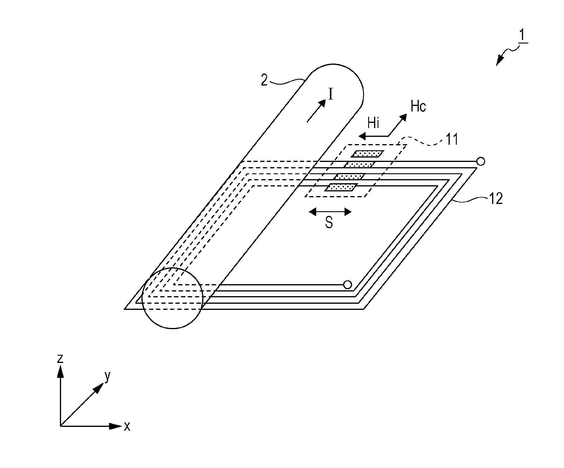
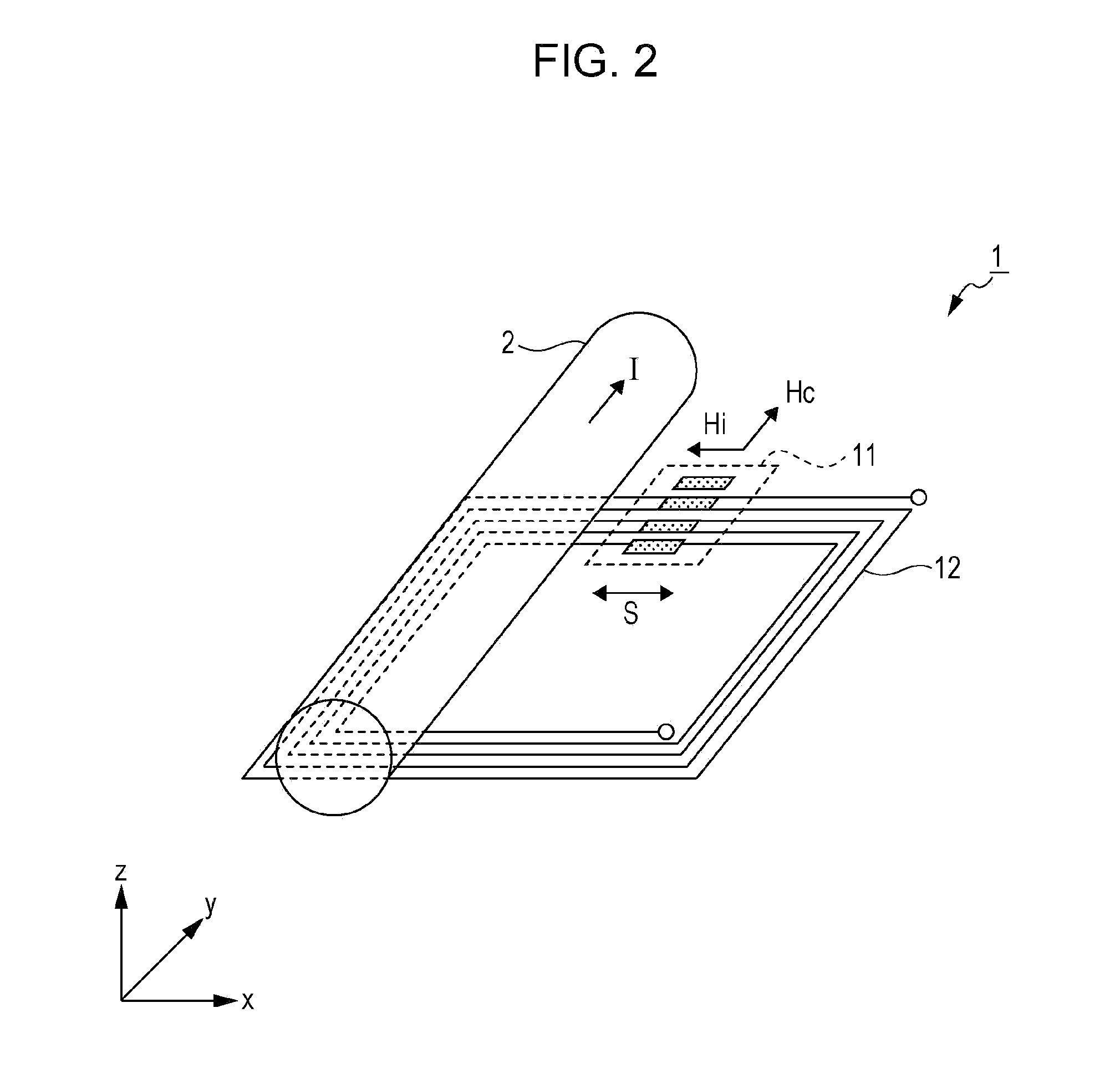
[0028]FIG. 2 and FIG. 3 are schematic diagrams illustrating example configurations of a current sensor according to the present embodiment. A current sensor 1 illustrated in FIG. 2 and FIG. 3 is a magnetic proportional current sensor, and is arranged near a current line 2 through which a measurement current I flows in the direction in which the current line 2 extends (y-direction).

[0029]The current sensor 1 illustrated in FIG. 2 and FIG. 3 includes a magnetic sensor 11 that detects an induction field Hi generated by the measurement current I flowing through the current line 2 and a coil (magnetic field application unit) 12 that can apply an induction field Hc with a predetermined direction to the magnetic sensor 11. In FIG. 3, the coil 12 is omitted for simplicity.

[0030]Referring to FIG. 3, the magnetic sensor 11 is formed of a bridge circuit that includes four magnetoresistive sensors 11a to 11d. Sensitivity directions (sensitivity axis directions) Sa to Sd of the magnetoresistive ...

second embodiment

[0057]In the present embodiment, a current sensor that calculates a compensation value using a method that is different from that in the above-described embodiment is described. Since the configuration of the current sensor according to the present embodiment is similar to that of the above-described embodiment, the detailed description thereof is omitted.

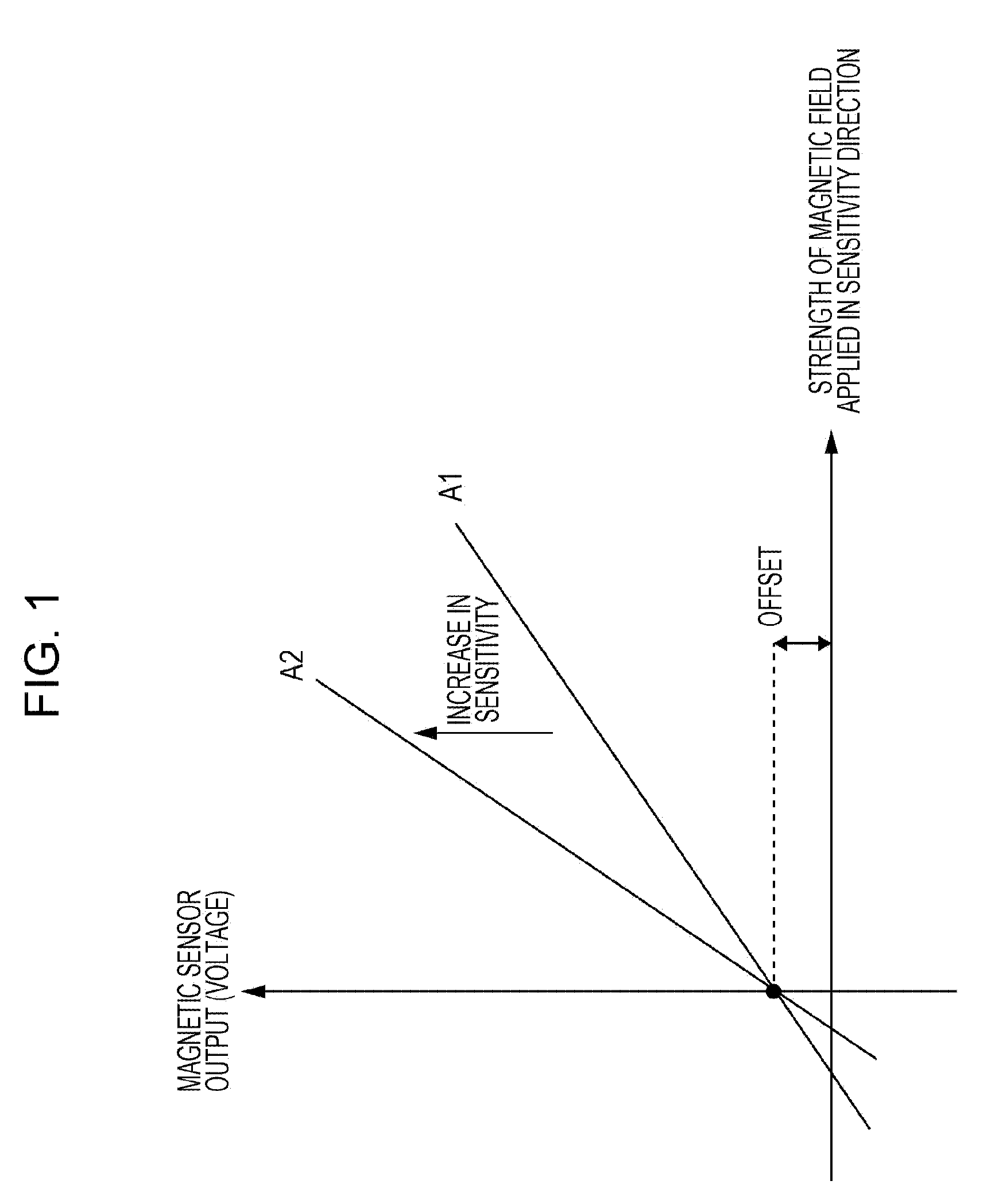
[0058]The current sensor according to the present embodiment may calculate a compensation value by applying two different induction fields using the coil 12. FIG. 8 is an output characteristic diagram of the magnetic sensor 11 in the case where a weak induction field Hc1 is applied by the coil 12 and the case where a strong induction field Hc2 is applied by the coil 12. In FIG. 8, the output characteristic of the magnetic sensor 11 in the case where the weak induction field Hc1 is applied by the coil 12 is denoted by B1, and the output characteristic of the magnetic sensor 11 in the case where the strong induction field Hc2 is appl...


PUM


Abstract

A current sensor includes a magnetic sensor including magnetoresistive sensors configured to detect induction fields generated by a measurement current passing through a current line, a magnetic field application unit configured to apply to the magnetoresistive sensors a magnetic field having a direction perpendicular to sensitivity directions of the magnetoresistive sensors; and a computing unit configured to calculate from an output of the magnetic sensor a compensation value for the output. The computing unit is configured to be capable of calculating the compensation value from the outputs of the magnetic sensor obtained in at least two states in which magnetic fields applied by the magnetic field application unit are different from each other.

Description

CLAIM OF PRIORITY[0001]This application claims benefit of Japanese Patent Application No. 2011-214371 filed on Sep. 29, 2011, which is hereby incorporated by reference.BACKGROUND OF THE INVENTION[0002]1. Field of the Invention[0003]The present invention relates to current sensors capable of measuring a current to be measured in a non-contact manner.[0004]2. Description of the Related Art[0005]Known current sensors in the areas of electric cars, solar batteries, and the like include a current sensor in which an induction field generated by a measurement current is detected using a magnetoresistive sensor, which is a magnetic sensor (refer to US2006 / 071655A1, for example). In a current sensor disclosed in US2006 / 071655A1, a high sensitivity is realized by detecting a measurement current on the basis of differences among a plurality of the outputs of magnetoresistive sensors.[0006]In such a current sensor, since the magnetic field detection sensitivity of a magnetoresistive sensor dire...

Claims


Application Information

Patent Timeline
Patent Type & Authority Patents(United States)
IPC IPC(8): G01R33/02G01R15/20G01R31/00G01R33/09
CPCG01R15/205G01R33/09G01R33/091G01R31/006
Inventor FUKUI, HIROFUMI
Owner ALPS ALPINE CO LTD
Why Eureka
Try Eureka