Multiple chamber medication dispensing apparatus

a medication dispensing and multi-chamber technology, applied in the direction of medical syringes, infusion syringes, automatic syringes, etc., can solve the problems of insufficient dose accuracy for some applications, large plunging force required to advance the cartridge piston during an injection, and limit the amount of medicine contained, etc., to achieve accurate administration of small volume doses, high dose accuracy, and high potency drugs

Inactive Publication Date: 2007-03-15
ELI LILLY & CO
View PDF14 Cites 78 Cited by
  • Summary
  • Abstract
  • Description
  • Claims
  • Application Information

AI Technical Summary

Benefits of technology

[0007] One advantage of the present invention is that a medication dispensing apparatus can be provided with a small area injection chamber that permits injections to be performed with a low glide force, which low glide force can allow for a direct injection as opposed to a mechanically assisted injection.
[0008] Another advantage of the present invention is that a medication dispensing apparatus can be provided which uses multiple chambers, but which outwardly appears to operate similar to some conventional injector pens.
[0009] Another advantage of the present invention is that a medication dispensing apparatus can be provided with high dose accuracy, and which can accurately administer small volume doses, thereby being useful for high potency drugs.
[0010] Still another advantage of the present invention is that a medication dispe

Problems solved by technology

One shortcoming of some injector pens is that the plunging force required to advance the cartridge piston during an injection may be too large for some users, such as those with limited hand strength, possibly due to the disease being treated.
Another shortcoming of some injector pens is that the drive member motion results in a dose accuracy that may be insufficient for some applications.
And, while for a given drive member motion, a smaller diameter conventional cartridge in a pen generally can be used to obtain higher dose accuracy, such a sma

Method used


Image

  • Multiple chamber medication dispensing apparatus
  • Multiple chamber medication dispensing apparatus
  • Multiple chamber medication dispensing apparatus

Examples


Embodiment Construction

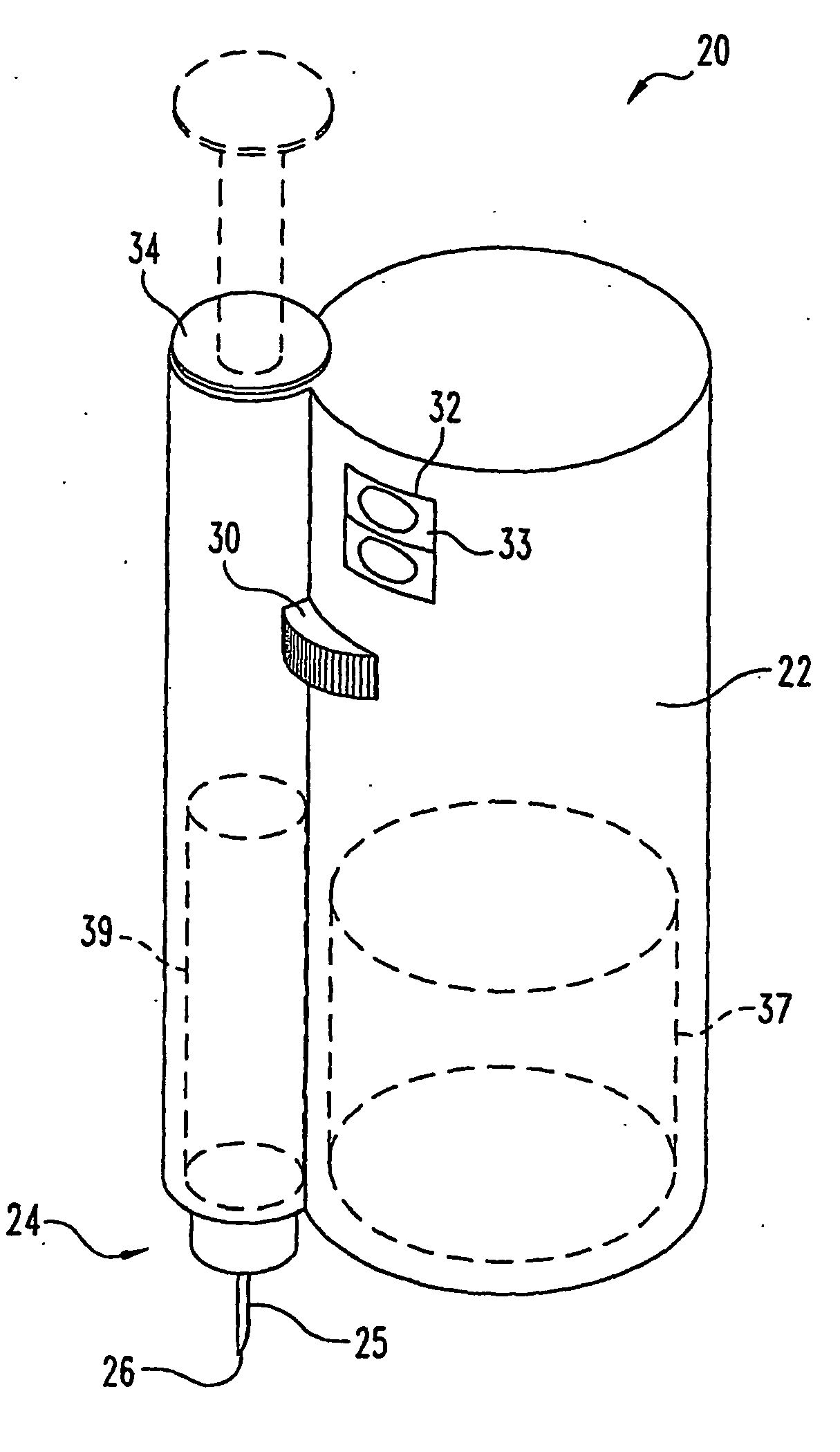
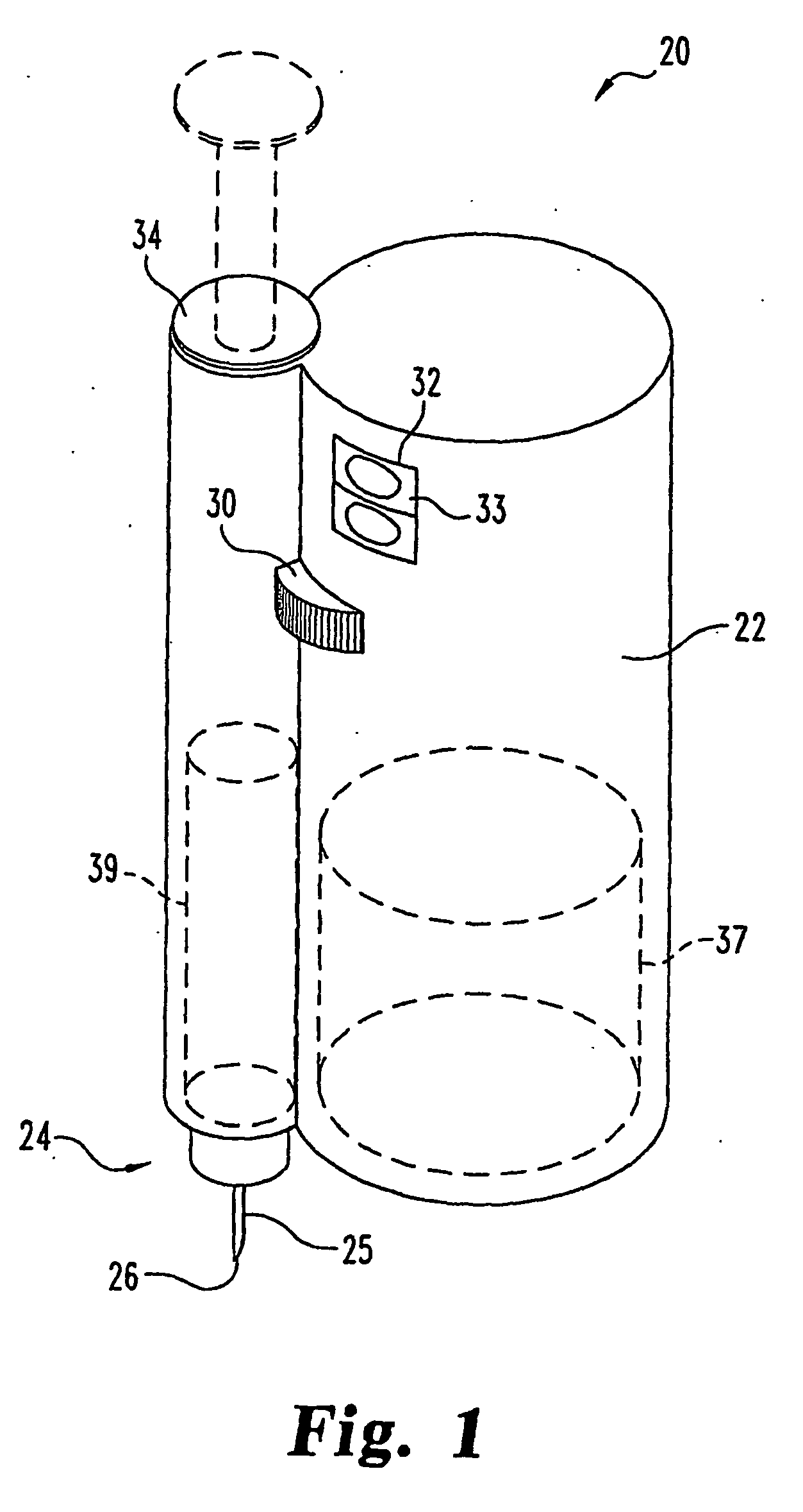
[0022] Referring now to FIG. 1, there is shown a first embodiment of a medication dispensing apparatus with multiple chambers of the present invention. The apparatus, generally designated 20, is an injector pen that is portable by a user to discreetly administer, at any appropriate time and place, a dose of medication selected by the user. Injector pen 20 is shorter and wider in overall shape than some more conventionally shaped injector pens, but such shape results in a desirably compact design, and further can be modified within the scope of the invention.

[0023] Medication injector pen 20 is a disposable or prefilled pen, in that after the quantity of medicine contained therein is exhausted by multiple operations of the pen, the entire pen is discarded rather than being reset and reloaded with a replacement container of medicine. As the pen has a relatively short working life, the pen components are preferably molded from one or more polymeric materials such as plastic when possi...


PUM


Abstract

A medication dispensing apparatus that can be actuated with a small force to deliver a precise dose. The apparatus includes a fluid container having an injection chamber and a storage chamber in fluid flow communication. A first plunger is movable to alter the volume of the injection chamber, and a second plunger is movable to alter the volume of the storage chamber. The injection chamber has a cross-sectional area that is smaller than a cross-section area of the storage chamber. During dose setting, a drive assembly drivingly connected to the plungers shifts the plungers different distances so as to reduce the volume of the storage chamber while simultaneously increasing the volume of the injection chamber a similar amount. After dose setting, an actuator is movable with a small force to shift the first plunger to reduce the volume of the injection chamber to force medicine through an outlet of the fluid container.

Description

BACKGROUND OF THE INVENTION [0001] The present invention pertains to:medication dispensing devices, and, in particular to a portable medication dispensing device such as an injector pen. [0002] Patients suffering from a number of different diseases frequently must inject themselves with medication. To allow a person to conveniently and accurately self-administer medicine, a variety of devices broadly known as injector pens or injection pens have been developed. Generally, these pens are equipped with a cartridge including a piston and containing a multi-dose quantity of liquid medication. A drive member, extending from within a base of the injector pen and operably connected with typically more rearward mechanisms of the pen that control drive member motion, is movable forward to advance the piston in the cartridge in such a manner to dispense the contained medication from an outlet at the opposite cartridge end, typically through a needle that penetrates a stopper at that opposite ...

Claims


Application Information

Patent Timeline
IPC IPC(8): A61M5/00A61M5/19A61M5/20A61M5/315
CPCA61M5/19A61M5/20A61M5/204A61M5/31511A61M5/31525A61M5/31553A61M2005/3152A61M5/31573A61M5/31575A61M5/3158A61M5/31581A61M2005/3125A61M5/31558
Inventor DAI, HEMORRISON JR, WILLIAM HAROLDNESBITT, ROBERT RICHARDSONSCHAFF SR, ANTHONY LAWRENCE
Owner ELI LILLY & CO
Why Eureka
Try Eureka