High strength, low density metal matrix composite ball sealer

a composite, high-density technology, applied in the direction of sealing/packing, fluid removal, borehole/well accessories, etc., can solve the problems of limiting the use of materials and constructions, and the range is relatively low

Active Publication Date: 2014-10-07
PARKER INTANGIBLES LLC
View PDF20 Cites 45 Cited by
  • Summary
  • Abstract
  • Description
  • Claims
  • Application Information

AI Technical Summary

Problems solved by technology

This range is relatively low and limits the ma

Method used


Image

  • High strength, low density metal matrix composite ball sealer
  • High strength, low density metal matrix composite ball sealer
  • High strength, low density metal matrix composite ball sealer

Examples


Embodiment Construction

[0021]Certain terminology may be employed in the description to follow for convenience rather than for any limiting purpose. For example, the terms “forward,”“rearward,”“right,”“left,”“upper,” and “lower” designate directions in the drawings to which reference is made, with the terms “inward,”“interior,”“inner,” or “inboard” and “outward,”“exterior,”“outer,” or “outboard” referring, respectively, to directions toward and away from the center of the referenced element, and the terms “radial” or “horizontal” and “axial” or “vertical” referring, respectively, to directions, axes, planes perpendicular and parallel to the central longitudinal axis of the referenced element. Terminology of similar import other than the words specifically mentioned above likewise is to be considered as being used for purposes of convenience rather than in any limiting sense.

[0022]In the figures, elements having an alphanumeric designation may be referenced herein collectively or in the alternative, as will...


PUM


Abstract

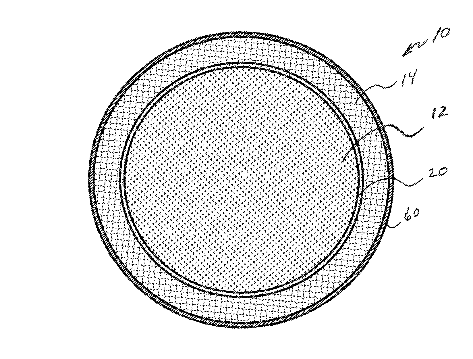
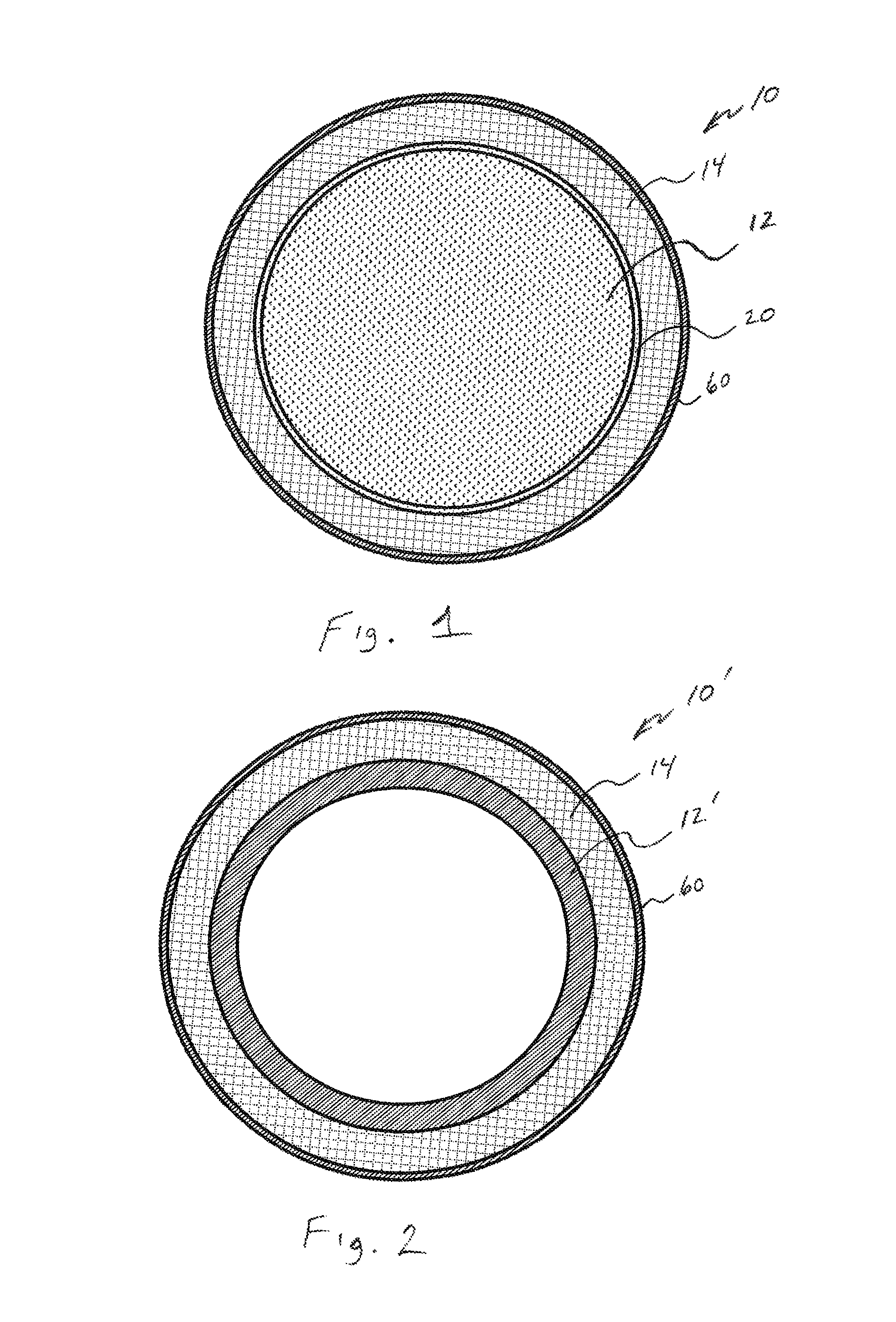
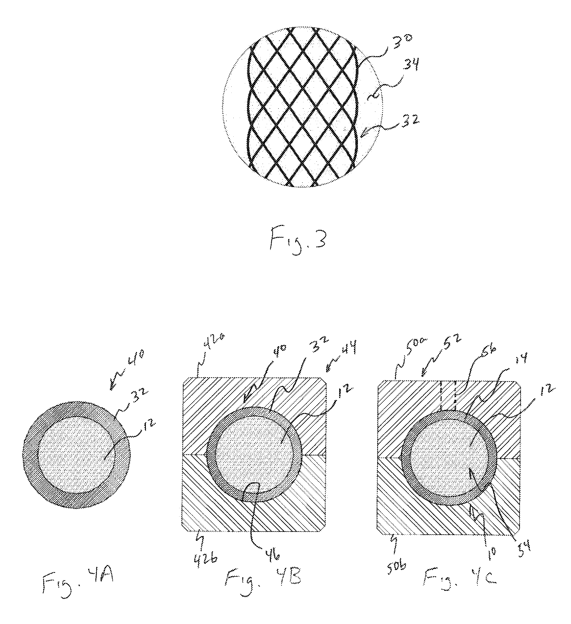
High strength, low density ball sealer for sealing openings in oil or gas wells, such as perforations formed through the well casing or openings formed through slidable packers or sleeves received within a tubing string in the well, from the flow of a fluid injected into the well. The ball sealer is formed as having an inner core, and a metal matrix composite layer surrounding the core.

Description

CROSS REFERENCE TO RELATED APPLICATIONS[0001]The present application claims the benefit of the filing date of U.S. Provisional Application Ser. No. 61 / 233,168, filed Aug. 12, 2009, the disclosure of which is incorporated herein by reference in its entirety.FIELD OF THE INVENTION[0002]The present invention relates broadly to ball sealers used for sealing perforations in the casings of wellbores such as during stimulation operations.BACKGROUND OF THE INVENTION[0003]As described in U.S. Pat. Nos. 2,254,246; 4,244,425; 4,410,387; and 4,505,334; U.S. Pat. Appln. Publ. 2009 / 0255674, and Intl. Appln. No. WO 2009 / 050681, it is common practice in completing oil and gas wells to set a string of pipe, also known as a casing, in the wellbore. The outside of the casing typically is surrounded by concrete sheath. Perforations are provided through the sheath and casing to allow fluid to flow between the interior of the casing and the geological formations surrounding the sheath. This structure of ...

Claims


Application Information

Patent Timeline
IPC IPC(8): E21B33/13
CPCE21B33/138
Inventor DUDZINSKI, PAUL, A.
Owner PARKER INTANGIBLES LLC
Why Eureka
Try Eureka