
Elevator tension member monitoring device

a technology of tension member and monitoring device, which is applied in the direction of tension measurement, apparatus for force/torque/work measurement, elevators, etc., can solve the problems of wear and tear of wires or strands that constitute ropes, and achieve the effect of being convenient to use and inexpensiv

Active Publication Date: 2014-10-07
OTIS ELEVATOR CO
View PDF26 Cites 8 Cited by
  • Summary
  • Abstract
  • Description
  • Claims
  • Application Information

AI Technical Summary

Benefits of technology

The present invention aims to provide a cheaper and easier elevator rope monitoring device to detect rope defects. This resolution enables early detection and timely replacement of rope defects, thereby ensuring safe and reliable elevator operation.

Problems solved by technology

Breakage, wear and the like sometimes occur in the wires or strands that constitute the rope due to the effects of frequent bending, tensile stress, abrasion, etc.

Method used


Image

  • Elevator tension member monitoring device
  • Elevator tension member monitoring device
  • Elevator tension member monitoring device

Examples


Embodiment Construction

[0052]Embodiments of the invented elevator tension member defect determining device according to the present invention are explained below based on figures. Efforts have been made throughout the drawings to use the same or similar reference numerals for the same or like components.

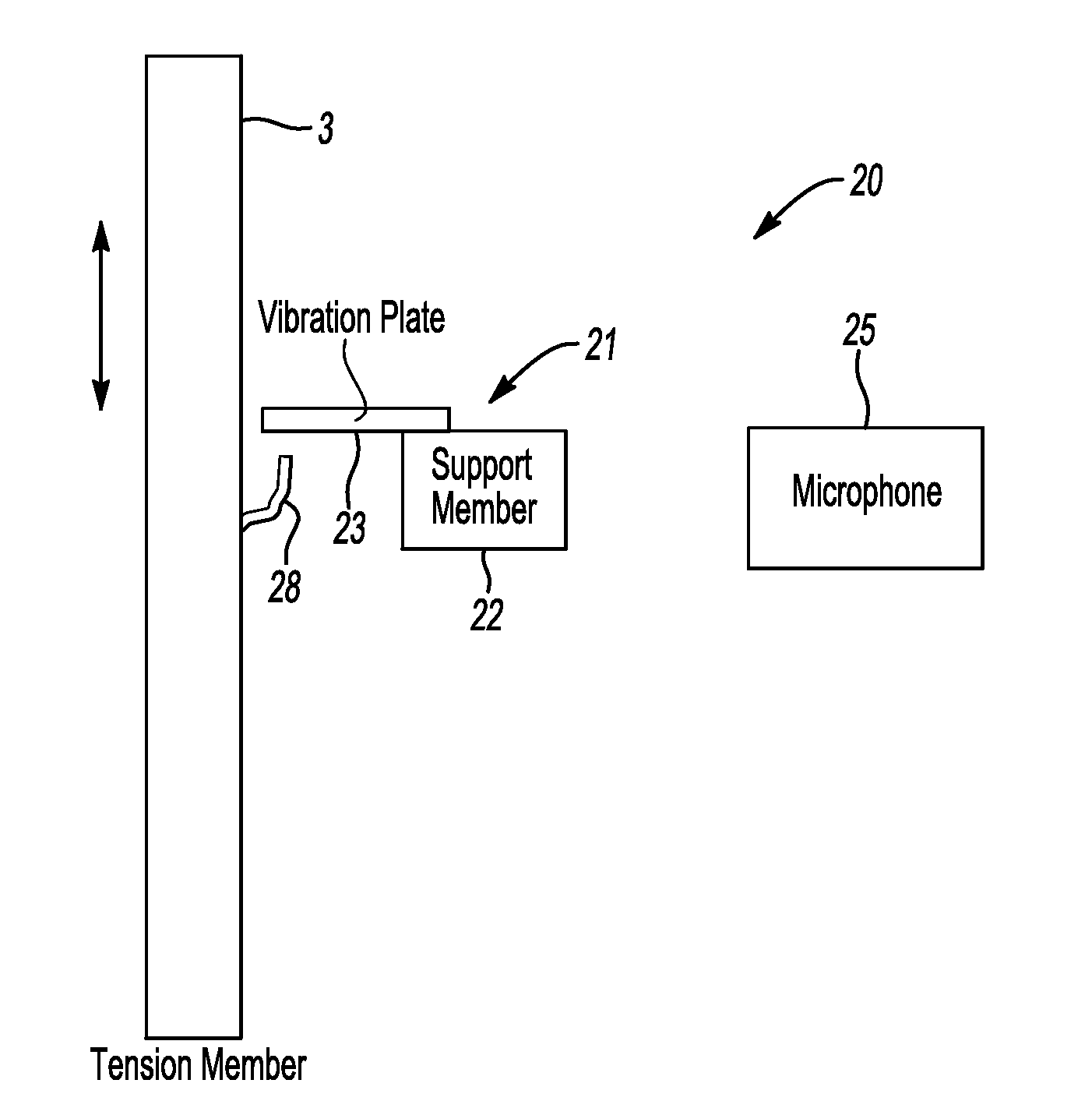
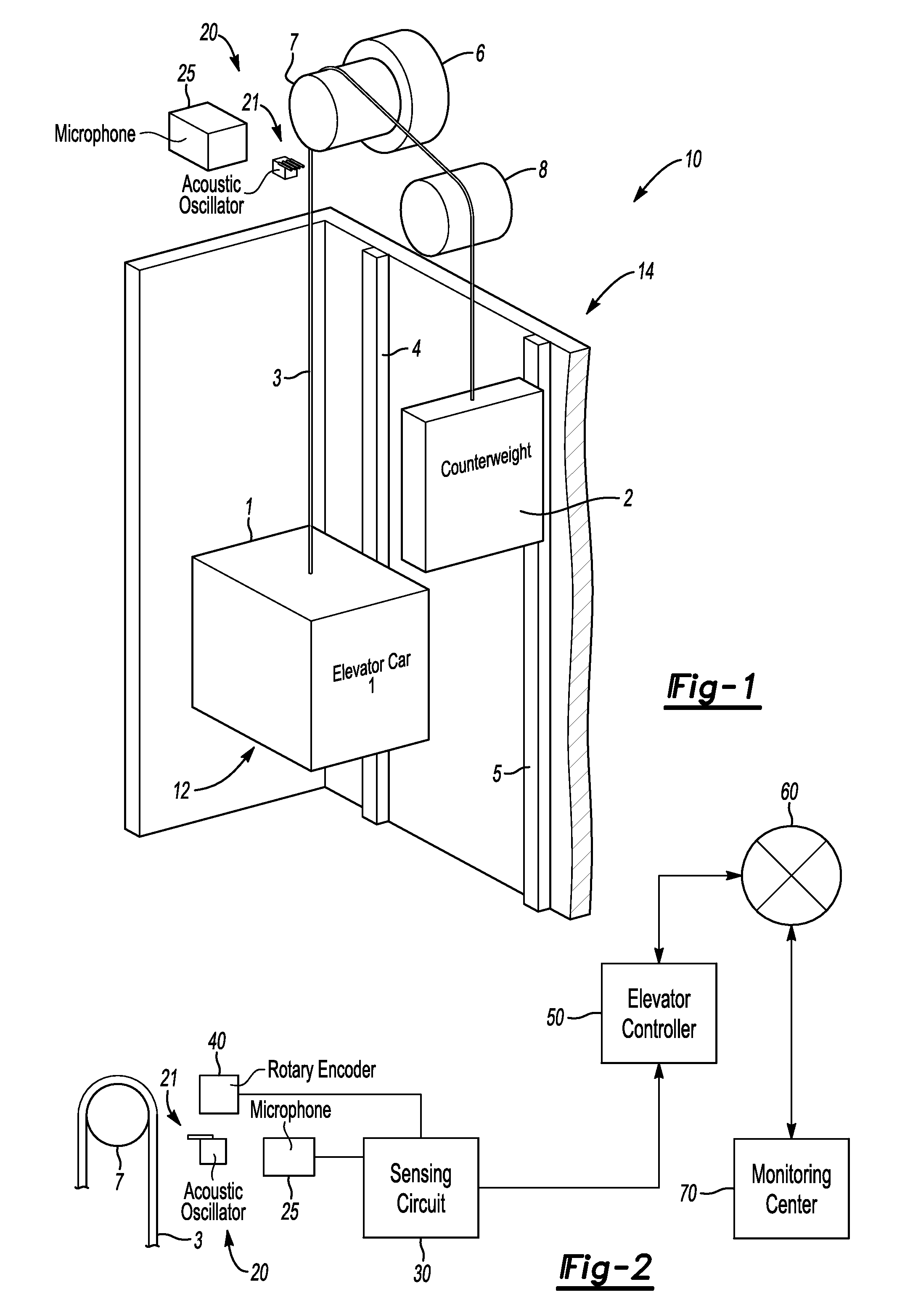
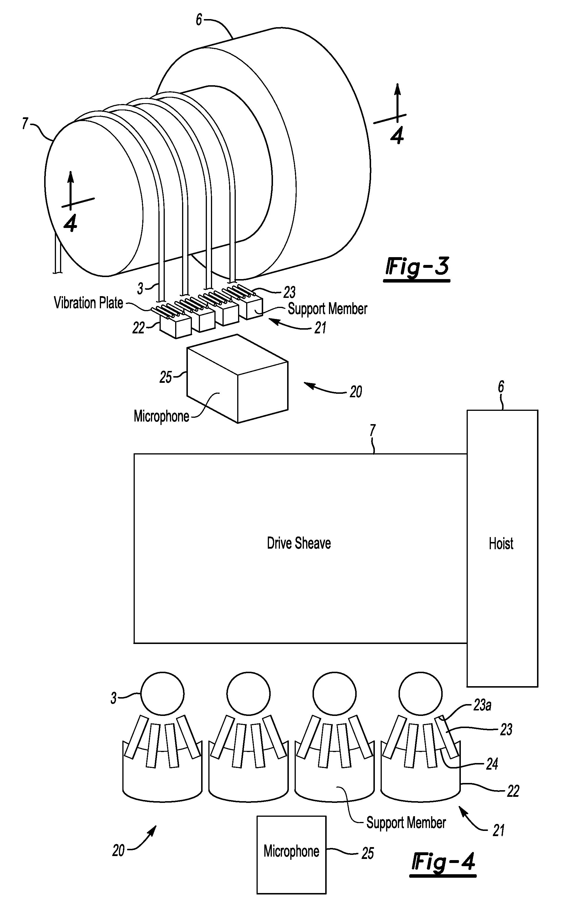
[0053]Referring to the figures, hoist 6 provided with drive sheave 7 is installed in machine room 14 positioned at the uppermost part of hoistway 12. One end of at least one elevator tension member 3 is connected to elevator car 1, and the other end is connected to counterweight 2. When the tension member 3 (which may be, for example, a wire rope, a belt, etc.) is driven by hoist 6 via idler sheave 8 and drive sheave 7 provided with hoist 6, car 1 and counterweight 2 respectively move along car guide rails 4 (one of which is shown in FIG. 1) and counterweight guide rails 5 (again, one of which is shown in FIG. 1).

[0054]Tension member defect determining device 20 of the present invention is provided with at...


PUM


Abstract

A tension member monitoring device is provided with at least one contact sensor (21) and a defect determining device (20). The contact sensor (21), which is arranged next to a corresponding tension member (3) without touching the tension member (3), is configured to output a contact signal when contacted. The defect determining device (20), which receives the contact signal, is configured to determine whether there is a defect in the tension member (3), based on the contact signal.

Description

TECHNICAL FIELD[0001]This invention relates to elevator tension member monitoring device.BACKGROUND ART[0002]The present invention relates to a tension member monitoring device that monitors the tension member(s) used in an elevator system and senses defects therein. A typical elevator system includes a hoistway, a hoist positioned at the uppermost part of the hoistway, an elevator car guide rail and a counterweight guide rail mounted in the hoistway, and an elevator car and a counterweight that move up and down in the hoistway along the guide rails. The car and the counterweight are connected to each other by tension member such as a wire rope or belt (regardless of whether the belt itself contains a wire rope). The tension member is driven by the hoist, which moves the car and counterweight along the guide rails.[0003]A wire rope is typically constructed by twisting together strands made up of twisted multiple wires. Breakage, wear and the like sometimes occur in the wires or stra...

Claims


Application Information

Patent Timeline
Patent Type & Authority Patents(United States)
IPC IPC(8): B66B1/34B66B7/12
CPCB66B7/1215B66B7/12B66B11/08
Inventor NAKAMORI, MASANORI
Owner OTIS ELEVATOR CO
Learn More