Multi-level thermal air cooled LED light fixture

a led light fixture and thermal air cooling technology, which is applied in the direction of fixed installation, lighting and heating equipment, lighting support devices, etc., can solve the problems of increasing the size of the fixture, reducing the efficiency of convection removal, and not addressing the issue of heat build-up in the fixtur

Inactive Publication Date: 2014-10-07
GEORGE ERIK MCMILLAN
View PDF1 Cites 25 Cited by
  • Summary
  • Abstract
  • Description
  • Claims
  • Application Information

AI Technical Summary

Benefits of technology

[0010]In accordance with another form of this invention, there is provided a lighting fixture which includes a light emitting diode light source. The light emitting diode light source has a front side which emits light and a back side opposite the front side. A primary heat sink is attached to the back side of the light emitting diode light source. Preferably, a divider plate is used to create two separate planes. A thermally conductive material is recommended for the divider plate, such as aluminum, copper or other such material allowing greater thermal surface for heat transfer. A pass-through or cross-over vent or vents are preferably used to allow air to pass from the lower plane to the upper plane via said heat sink, mounted below the divider plate. Preferably, a void is incorporated in the heat sink's center and this void is situated directly in line and under one of the divider plate vent openings, allowing heated air to pass from the lower plane to the upper plane. To be more efficient, a secondary heat sink is preferably mounted directly above the primary heat sink via the divider plate and directly above the vent pass-through. The primary heat sink center void may remain hollow or created with thermal posts, rings or a cone, depending upon the LED or LED array used to develop the most effective thermal transfer method for the desired LED / LED array. This dual plane development for heat transfer creates a thermal chimney or “air thermal pump” which, due to the physics of moving heat or heated air upward through the cross-over vent, creates a partial vacuum in the lower plane and primary heat sink which, in turn, draws cool air into said lower plane. This system thus accelerates the thermal exchange and increases the cooling capabilities of the heat sink.

Problems solved by technology

There are several issues with these fixtures, whether they are T8 or T5 fluorescents or even LED retrofit kits or LED replacement fixtures.
In addition, recessed drop-in Troffers do not address the issue of heat build-up within the fixture.
A simple heat sink has the following cons: convection is slow in comparison with moving air systems; and convection is very limited in the ability to efficiently remove heat, thus, is only useable in small or mild heat applications.
A combined fan and heat sink has the following cons: fans increase the size and add to labor and time as they are an electric component; failure of the fan can cause overheating and damage to the component it is used to cool; fans produce noise; and fans consume energy.
Liquid cooling systems have the following cons: currently, still relatively expensive; most efficient liquid coolers are much larger than alternate systems limiting their usage; due to the necessity of the fan to cool the liquid or vapor, failure is a possibility which will cause serious damage to the component it is to cool; the fan aspect produces noise; and the fan aspect consumes energy.
The Peltier Plates method is, however, expensive and uses a fair amount of energy just to generate a cooling effect on one side while, at the same time, it builds heat on the other side that can cause a very hot surrounding especially if an additional fan is not used.
This actually creates two possible points of failure: failure of the Peltier Plate itself or failure of the cooling fan, wherein either failure would, in most applications, cause damage to the component it is used to cool.

Method used


Image

  • Multi-level thermal air cooled LED light fixture
  • Multi-level thermal air cooled LED light fixture
  • Multi-level thermal air cooled LED light fixture

Examples


Embodiment Construction

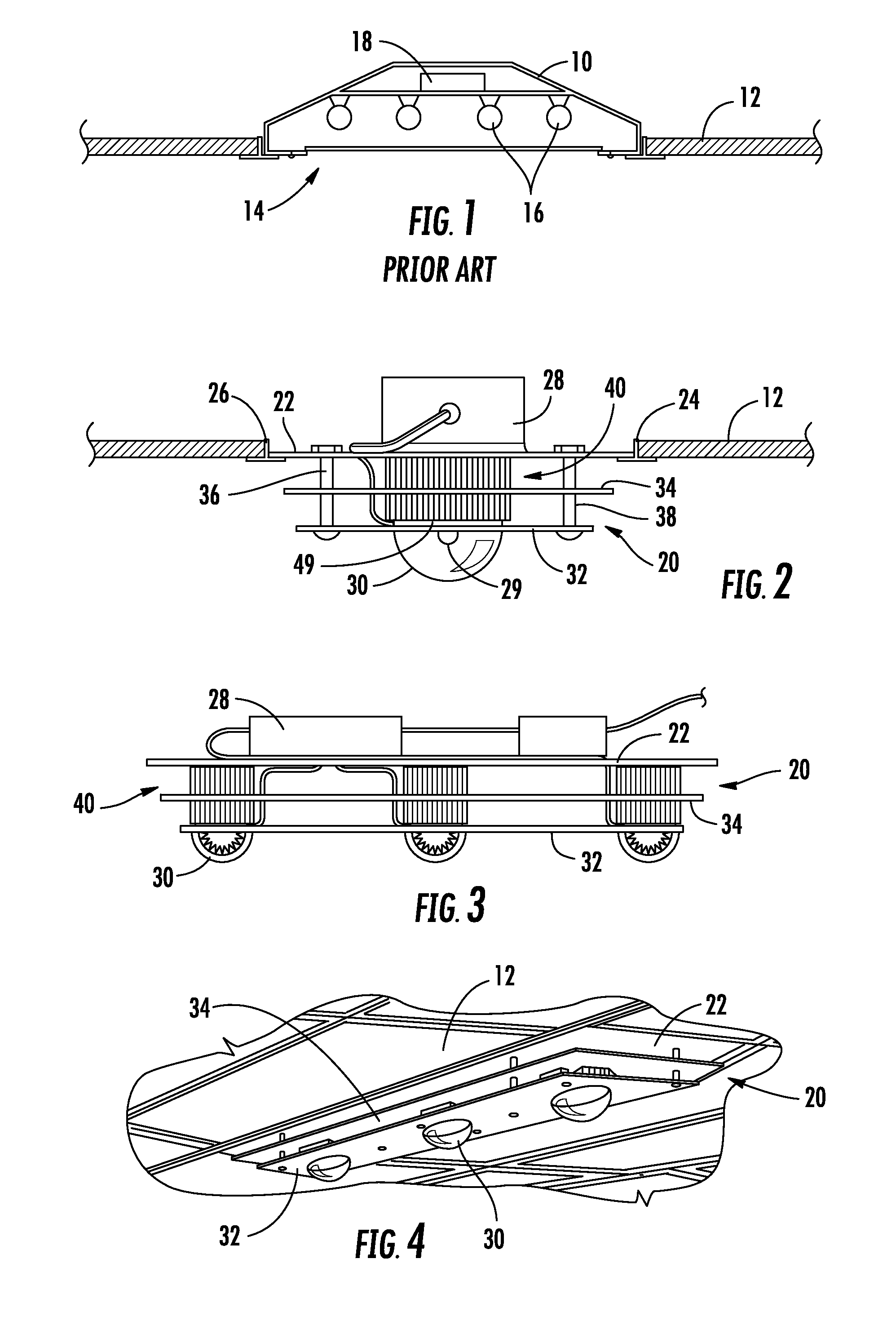
[0022]FIG. 1 shows a standard prior art fluorescent fixture 10 mounted to ceiling 12 within opening 14 in ceiling 12. Fixture 10 includes a plurality of fluorescent tubes 16. Ballast 18 is provided within fixture 10 to control fluorescent tubes 16. As can be seen, the entire fixture 10, including fluorescent tubes 16, is mounted above the plane of ceiling 12. Thus, light does not spread evenly from top to bottom of the walls within the room, nor does light impinge upon the ceiling. In addition, the standard fluorescent fixture is rather unattractive.

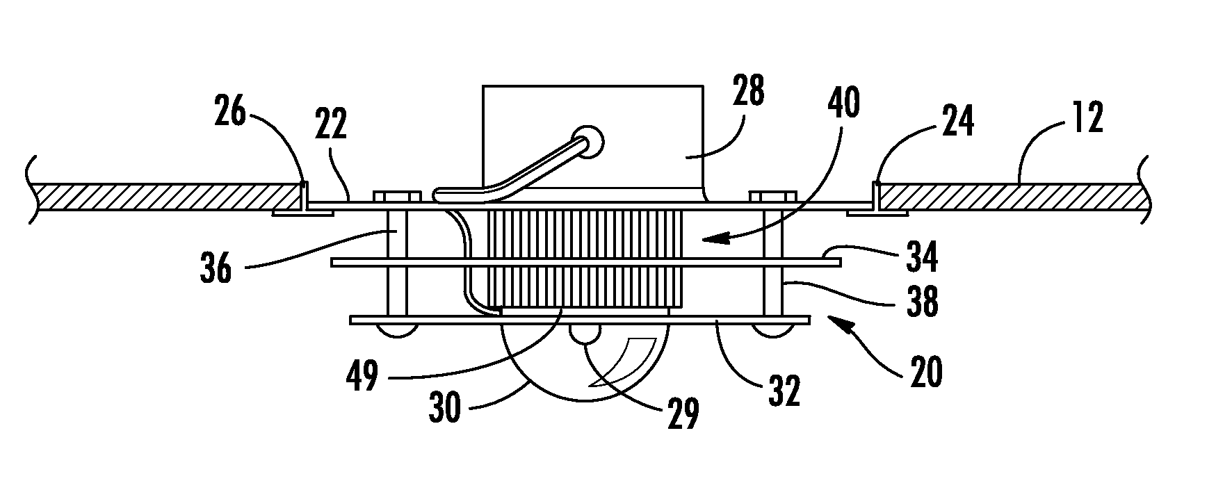
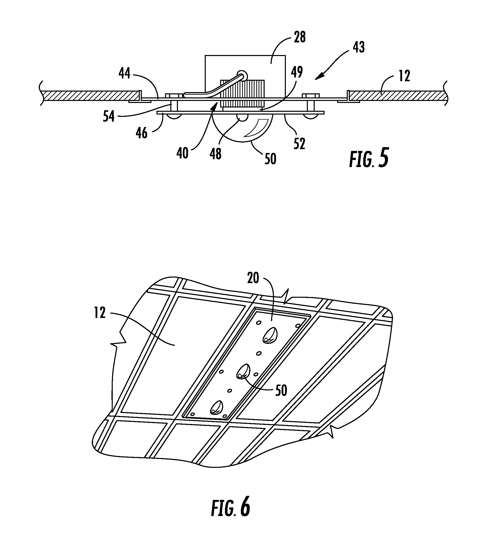
[0023]Applicant's designs illustrated in FIGS. 2-10, solve the problem of the lack of even light dispersion from floor to ceiling as well as the lack of aesthetics associated with prior art fixtures. Applicant has created an entirely new alternative to standard, every day, run-of-the-mill recessed drop-in Troffers-type fixtures. Applicant has developed a three dimensional multi-plate multi-lens drop-in fixture built for various panel ope...


PUM


Abstract

There is provided a lighting fixture adapted to be installed on a ceiling having a predetermined plane. A light emitting diode light source is supported by the lighting fixture. At least a portion of the lighting fixture protrudes below the plane of the ceiling supported by the lighting fixture. A heat sink is attached to the back side of the LED light source. The heat sink includes a thermal chimney directing heat away from the LED light source.

Description

RELATED APPLICATION[0001]This is a U.S. non-provisional application relating to and claiming the benefit of U.S. Provisional Patent Application Ser. No. 61 / 429,986 filed Jan. 5, 2011.BACKGROUND OF THE INVENTION[0002]For years, since the arrival of the drop-ceiling, Troffer drop-in fixtures have been used to light areas covered by such ceilings along with can lights and a few standard light fixture conversions. As the recessed drop-in Troffers go, (the 1′×4′, the 2′×4′ and the 2′×2′), they have all been nearly the same in regard to aesthetics. All have been designed with the light emitters or bulbs within the fixture located above the ceiling plane with a cover lens the same size as the light opening or have a simple grid within the opening, neither having much architectural design or artistic value. There are several issues with these fixtures, whether they are T8 or T5 fluorescents or even LED retrofit kits or LED replacement fixtures. Since the light source is above the ceiling pl...

Claims


Application Information

Patent Timeline
Patent Type & Authority Patents(United States)
IPC IPC(8): F21S8/00F21S8/02F21S8/04F21V21/04F21V29/00F21Y101/02
CPCF21V29/71F21V29/26F21S8/04Y10S362/80F21Y2101/02F21V29/2231F21V29/004F21S8/026F21V21/048F21V29/773F21Y2115/10F21V29/83
Inventor MCMILLAN, GEORGE, ERIK
Owner GEORGE ERIK MCMILLAN
Why Eureka
Try Eureka