
Apparatus for crystal growth

a vapour phase and crystal growth technology, applied in the direction of crystal growth process, crystal growth process, chemical vapor deposition coating, etc., can solve the problems of difficult control of crystal growth using such a system, unsuitable heaters such as resistance coil heaters

Active Publication Date: 2014-10-07
KROMEK
View PDF6 Cites 0 Cited by
  • Summary
  • Abstract
  • Description
  • Claims
  • Application Information

AI Technical Summary

Benefits of technology

This setup enhances thermal isolation and control over crystal growth, simplifies the system by avoiding vacuum requirements, and allows for efficient growth of bulk crystal materials with precise temperature differentials, reducing growth complexity and increasing heater flexibility.

Problems solved by technology

However, it is very difficult to control the growth of crystals using such a system.
Therefore, heaters such as resistance coil heaters are unsuitable.

Method used


Image

  • Apparatus for crystal growth
  • Apparatus for crystal growth
  • Apparatus for crystal growth

Examples


Embodiment Construction

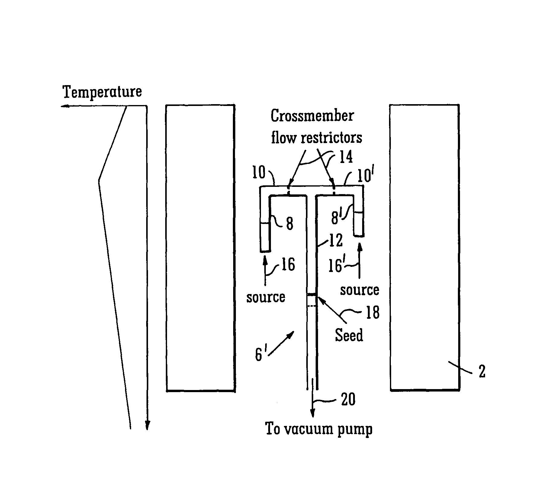
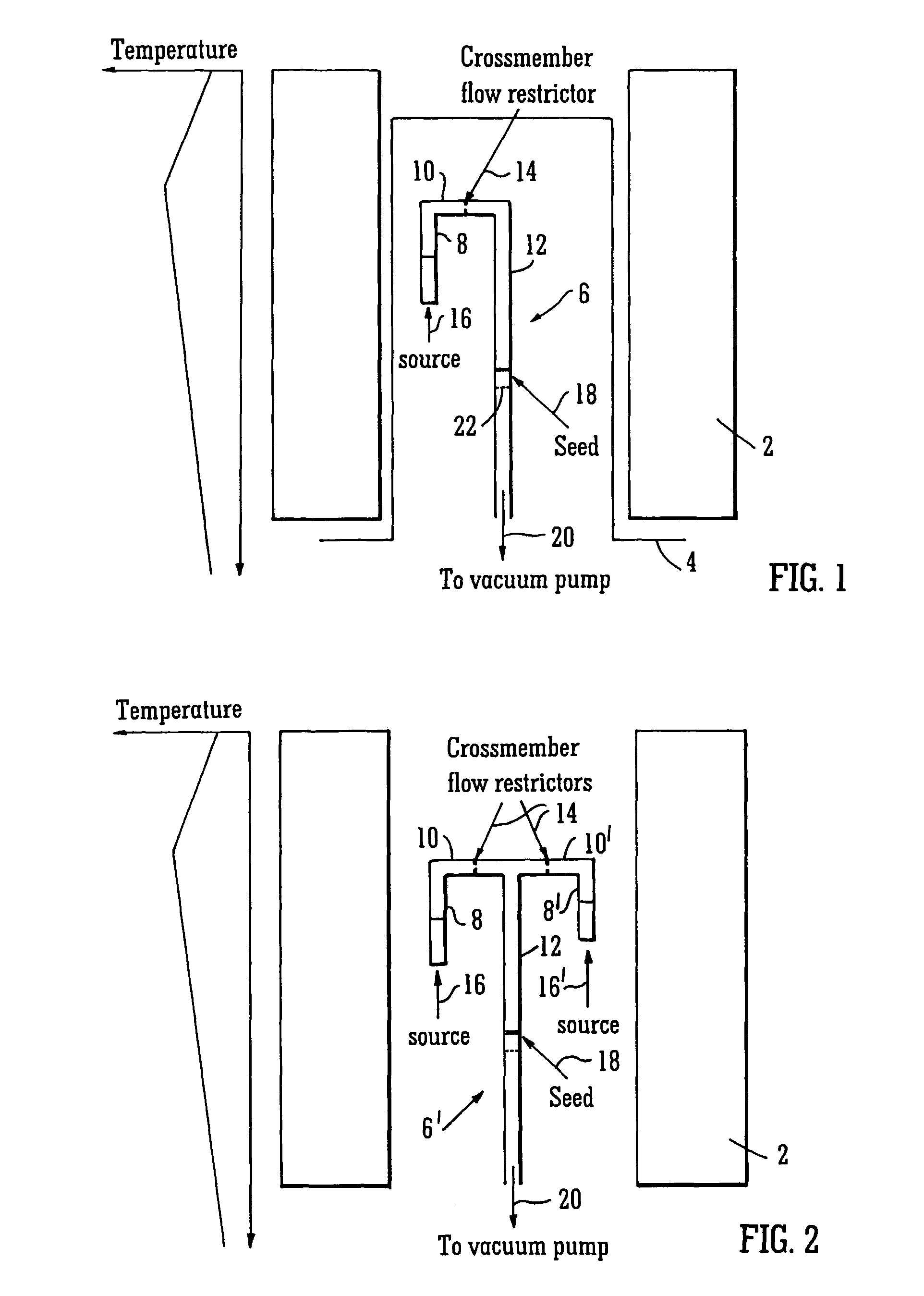
[0042]As shown in FIGS. 1 and 2, the apparatus of the present invention includes a multi-zone furnace 2. In the example shown, the furnace is in the form of an annular heater provided to heat a central heated region. It will be appreciated that the heater does not have to be an annular heater, but could for example be a planar heater arranged to heat the heated region from one side, or could comprise a number of heating elements arranged around the heated region. Optical heaters may also be used.

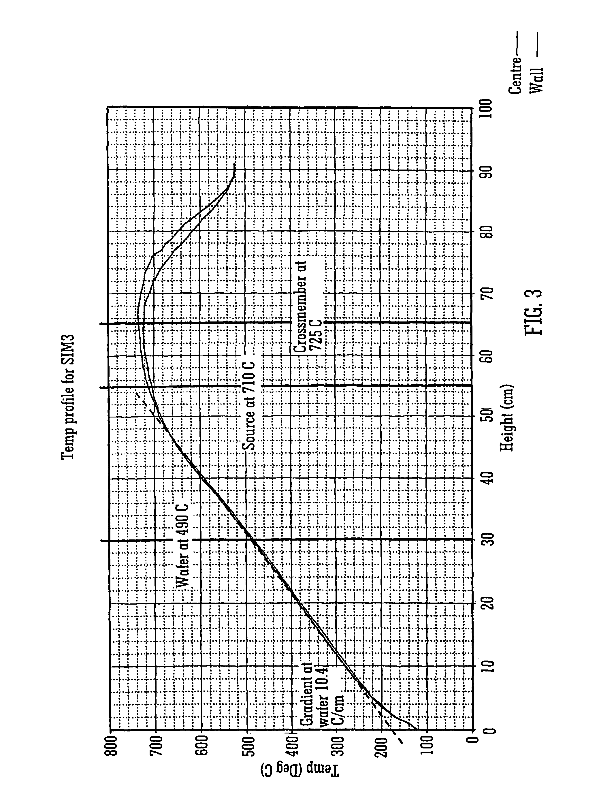
[0043]As shown in the temperature graph of FIG. 3, the multi-zone heater, which may include three main zones, heats the heated region to provide a predetermined temperature profile. In the example show, the maximum temperature is towards the top of the heater region, with a decreasing temperature above and below this maximum temperature region. The temperature profile is such that the temperature decreases from the maximum temperature at a greater rate above the maximum temperature region th...


PUM

PropertyMeasurementUnit
thicknessaaaaaaaaaa
temperaturesaaaaaaaaaa

Abstract

Apparatus for vapor phase growing of crystals having a single multi-zone heater arranged to heat a heated zone to give a predetermined temperature profile along the length of the heated zone. A generally U-shaped tube having a first limb, a second limb, and a linkage connecting the first and second limbs is located on the heated zone. The first limb contains a source material. The second limb supports a seed such that the source material and seed are spaced longitudinally within the heated zone to provide a predetermined temperature differential between the source and seed. The crystal is grown on the seed.

Description

FIELD OF THE INVENTION[0001]The present invention relates to an apparatus for vapour phase crystal growth.BACKGROUND TO THE PRESENT INVENTION[0002]To grow a crystal by vapour phase crystal growth techniques, it is necessary to provide a source of the materials from which the crystal is to be formed, and a seed onto which the crystal is grown from the source material. A transport zone links the source and sink zones. By creating a temperature difference between the source zone and the sink zone where the seed is provided, a vapour pressure difference will be created between the source and sink zones which acts as the driving force for crystal growth. The temperature of the source zone should be greater than the temperature of the sink zone.[0003]The control of the crystal growth will be dependent on a number of factors, including the source and sink temperatures and the vapour pressures.[0004]In early vapour phase crystal growth systems, the crystal was grown on a seed crystal provid...

Claims


Application Information

Patent Timeline
Patent Type & Authority Patents(United States)
IPC IPC(8): C30B23/06C23C16/42C30B25/10C30B29/48C30B35/00
CPCC30B23/06C30B29/48C30B25/10C30B35/002C23C16/42C23C16/46Y10T117/10
Inventor BASU, ARNABCANTWELL, BENROBINSON, MAX
Owner KROMEK
Learn More