Display panel and method for narrowing edges and increasing edge strength thereof

a technology of display panel and edge strength, which is applied in the manufacture of electrode systems, electric discharge tubes/lamps, instruments, etc., can solve the problems of relatively difficult narrowing process and non-compliance with requirements, and achieve the effect of increasing edge strength, strength loss, and reducing the width of the side fram

Active Publication Date: 2014-10-07
AU OPTRONICS CORP
View PDF15 Cites 9 Cited by
  • Summary
  • Abstract
  • Description
  • Claims
  • Application Information

AI Technical Summary

Benefits of technology

[0007]In order to resolve the above problems, the present invention provides a display panel and methods for narrowing edges and increasing edge strength, so as to effectively narrow the side frames of the display panel and increase the strength of side frames to meet the demand of narrowing edges of the display panel.
[0009]According to a second embodiment of the present invention, a method for increasing edge strength of a display panel is disclosed. The display panel includes a first substrate, a second substrate and a sealant, the sealant being disposed between the first substrate and the second substrate. The method for increasing edge strength includes the steps of providing the display panel, a grinding apparatus and a polishing apparatus; tilting the display panel so that the second substrate of the display panel and a grinding member of the grinding apparatus form a grinding angle; grinding the second substrate with the grinding apparatus to form a grinding end surface on the second substrate while the display panel is tilted at the grinding angle; and polishing the grinding end surface with the polishing apparatus to form an end surface.
[0016]According to the display panel and the methods for narrowing edges and increasing edge strength of the present invention, the width of the side frames can be decreased to between 0.35 mm and 1 mm, and the strength loss problem caused by edge narrowing can be effectively resolved. Therefore, the present invention is practical.

Problems solved by technology

However, the requirements are not met by means of narrowing the design only.
The panel strength needs to be considered when the side frames are narrowed, which makes the narrowing process relatively difficult.

Method used


Image

  • Display panel and method for narrowing edges and increasing edge strength thereof
  • Display panel and method for narrowing edges and increasing edge strength thereof
  • Display panel and method for narrowing edges and increasing edge strength thereof

Examples


Embodiment Construction

[0030]The making and use of the presently preferred embodiments are discussed in detail below. It should be appreciated, however, that the present invention provides many applicable inventive concepts that can be embodied in a wide variety of specific contexts. The specific embodiments discussed are merely illustrative of specific ways to make and use the invention, and do not limit the scope of the invention.

[0031]The display panel and the methods for narrowing edges and increasing edge strength of the present invention are described with appended drawings below.

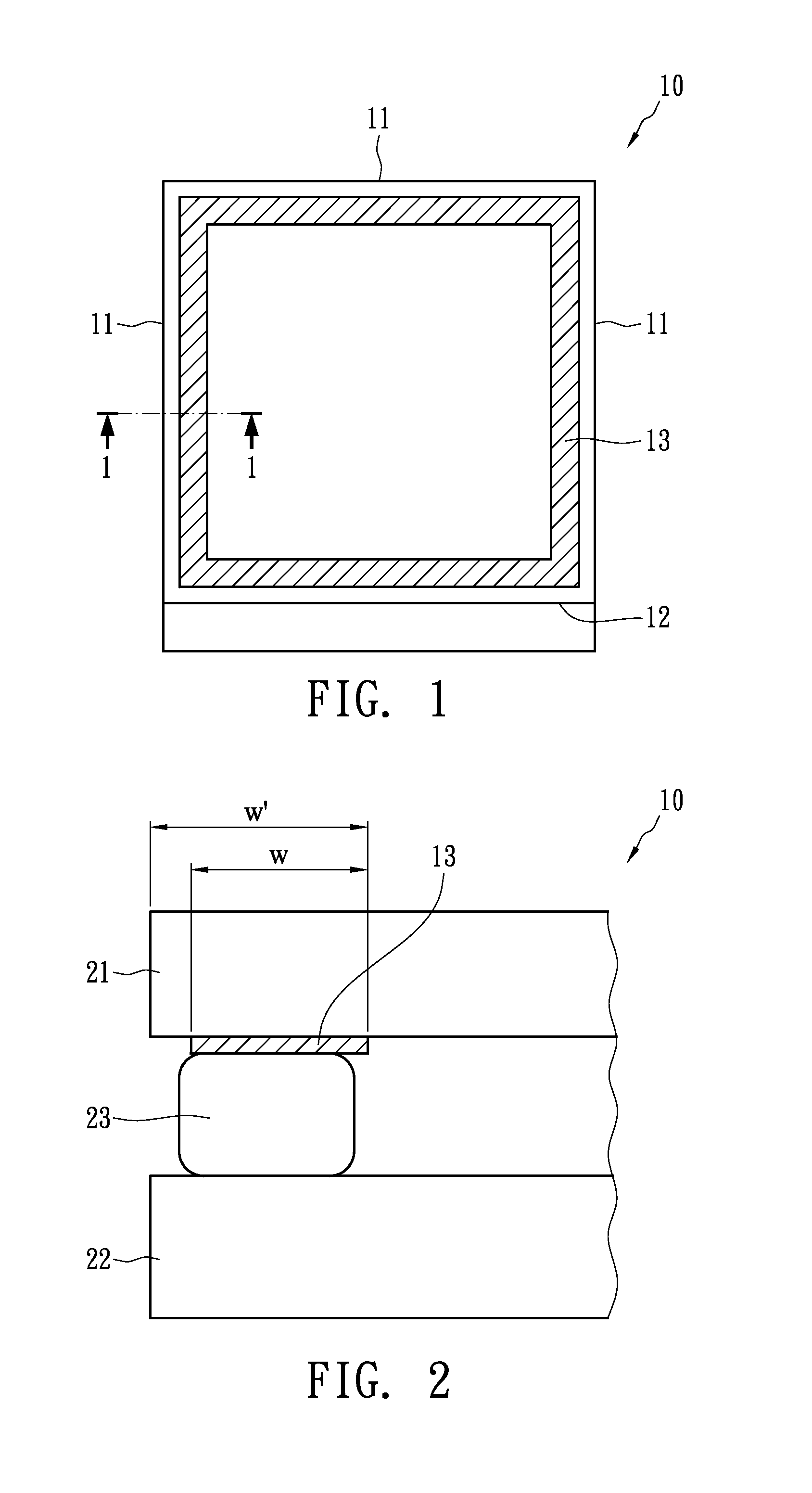
[0032]The method for narrowing edges of a display panel is stated as follows: FIG. 1 shows a top view of a display panel 10 including three first sides 11 and a second side 12. The second side 12 is used for connecting the circuits (not shown) in the display panel to external circuit boards (not shown). The three first sides 11 and the second side 12 are mutually connected. A light-shielding area 13 close to the first sides...


PUM

PropertyMeasurementUnit
widthaaaaaaaaaa
widthaaaaaaaaaa
roughness heightaaaaaaaaaa

Abstract

An edge narrowing method for a display panel is disclosed. The display panel includes a first substrate, a second substrate, a sealant and a light-shielding area. The sealant is disposed between the first substrate and the second substrate. The light-shielding area is disposed between the first substrate and the sealant. The method includes the steps of providing the display panel, a grinding apparatus and a polishing apparatus; tilting the display panel so that the first substrate and a grinding member of the grinding apparatus have a first grinding angle therebetween; grinding the first substrate and the light-shielding area with the grinding apparatus while the display panel is tilted at the first grinding angle, thereby forming a first grinding end surface; stopping grinding of the first substrate and the light-shielding area when the width of the light-shielding area is between 0.35 and 1 mm; and polishing the first grinding end surface with the polishing apparatus to form a first end surface.

Description

BACKGROUND OF THE INVENTION[0001](A) Field of the Invention[0002]The present invention relates to display panel technologies, and more specifically, to a liquid crystal display panel and methods for narrowing edges and increasing edge strength thereof.[0003](B) Description of Related Art[0004]Liquid crystal displays (LCD) have many advantages such as thin profile, light weight, low power consumption and low radiation, and therefore are widely used in current display applications. An LCD display primarily includes an LCD panel and a back light unit. The back light unit serves as an illumination source for the LCD panel, and the rotations of the liquid crystals are controlled by electrical signals so as to display images.[0005]As the technology of portable mobile apparatus advances, in order to meet demands of artistic appearance and miniature size, the side frames of the display panel need to be narrowed. However, the requirements are not met by means of narrowing the design only. Th...

Claims


Application Information

Patent Timeline
Patent Type & Authority Patents(United States)
IPC IPC(8): G02F1/1339G02F1/1333
CPCG02F1/1333H01J2209/267B24B9/06Y10T428/24355G02F2001/133388Y10T83/04G02F1/1339G02F1/1341G02F1/133388
Inventor LIU, YU CHENLIU, CHUNG WEIWANG, SHU CHIHWENG, CHIA SHIN
Owner AU OPTRONICS CORP
Why Eureka
Try Eureka