Multi-stage compressor in a plasma cutter

a plasma cutter and compressor technology, applied in the direction of machines/engines, positive displacement liquid engines, manufacturing tools, etc., can solve the problems of affecting the performance of the system, affecting the cutting speed of plasma cutters, and causing the cutters to overheat,

Inactive Publication Date: 2014-10-14
ILLINOIS TOOL WORKS INC
View PDF36 Cites 22 Cited by
  • Summary
  • Abstract
  • Description
  • Claims
  • Application Information

AI Technical Summary

Problems solved by technology

The power output and flow of the gas can affect the performance of the system.
Any reduction in pressure and flow of the air may cause the torch to overheat, cut slower or cut at unacceptable rates, and blow away the molten metal or other material less effectively.
Additionally, the efficiency of the compressor can affect the power used by the system and the heat generated by the system, thus impacting operating costs and cooling requirements.
Further, excessive heat, vibration, and / or movement of the compressor may damage or prematurely wear adjacent components and / or the compressor itself.

Method used


Image

  • Multi-stage compressor in a plasma cutter
  • Multi-stage compressor in a plasma cutter
  • Multi-stage compressor in a plasma cutter

Examples


Embodiment Construction

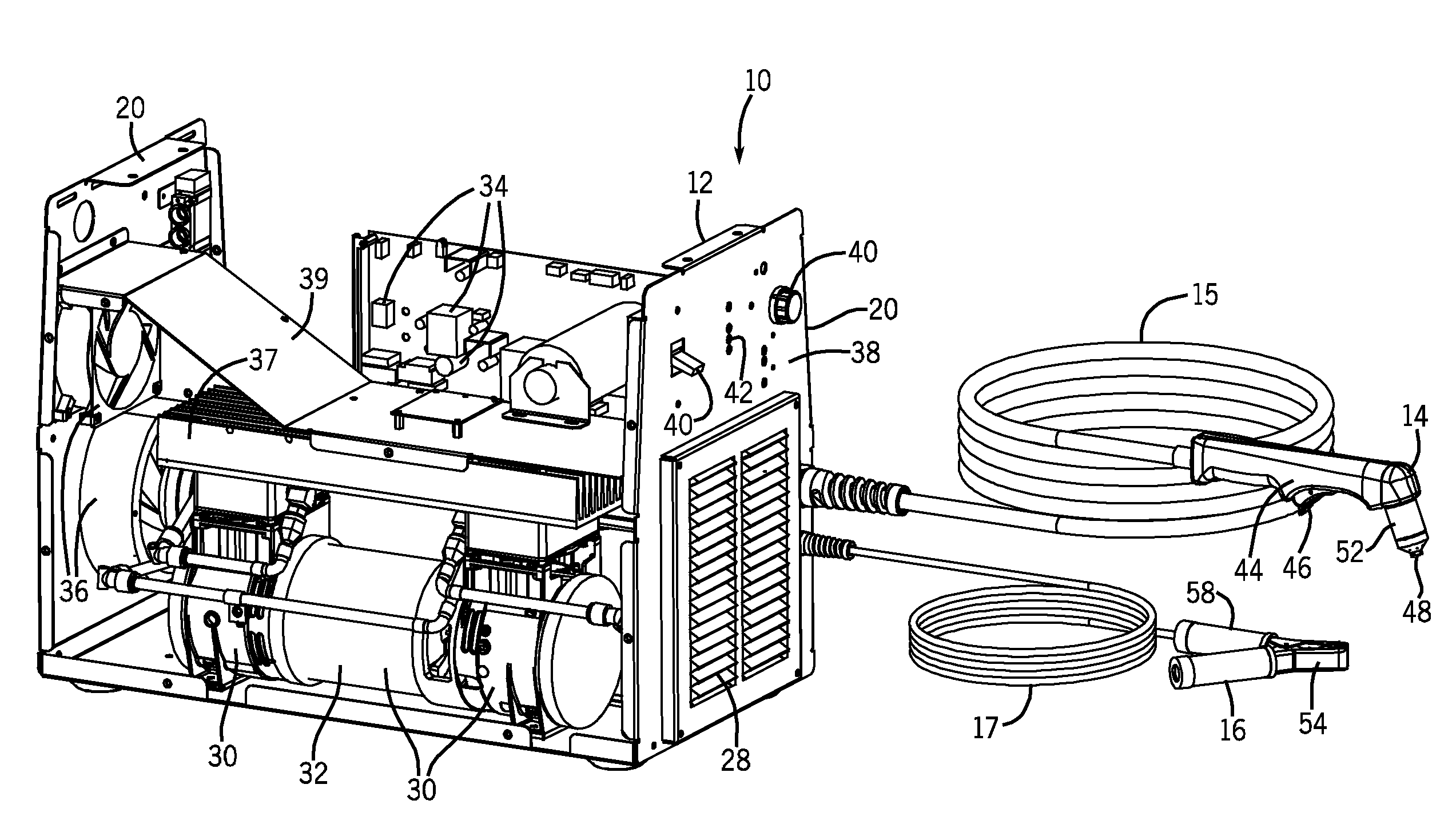
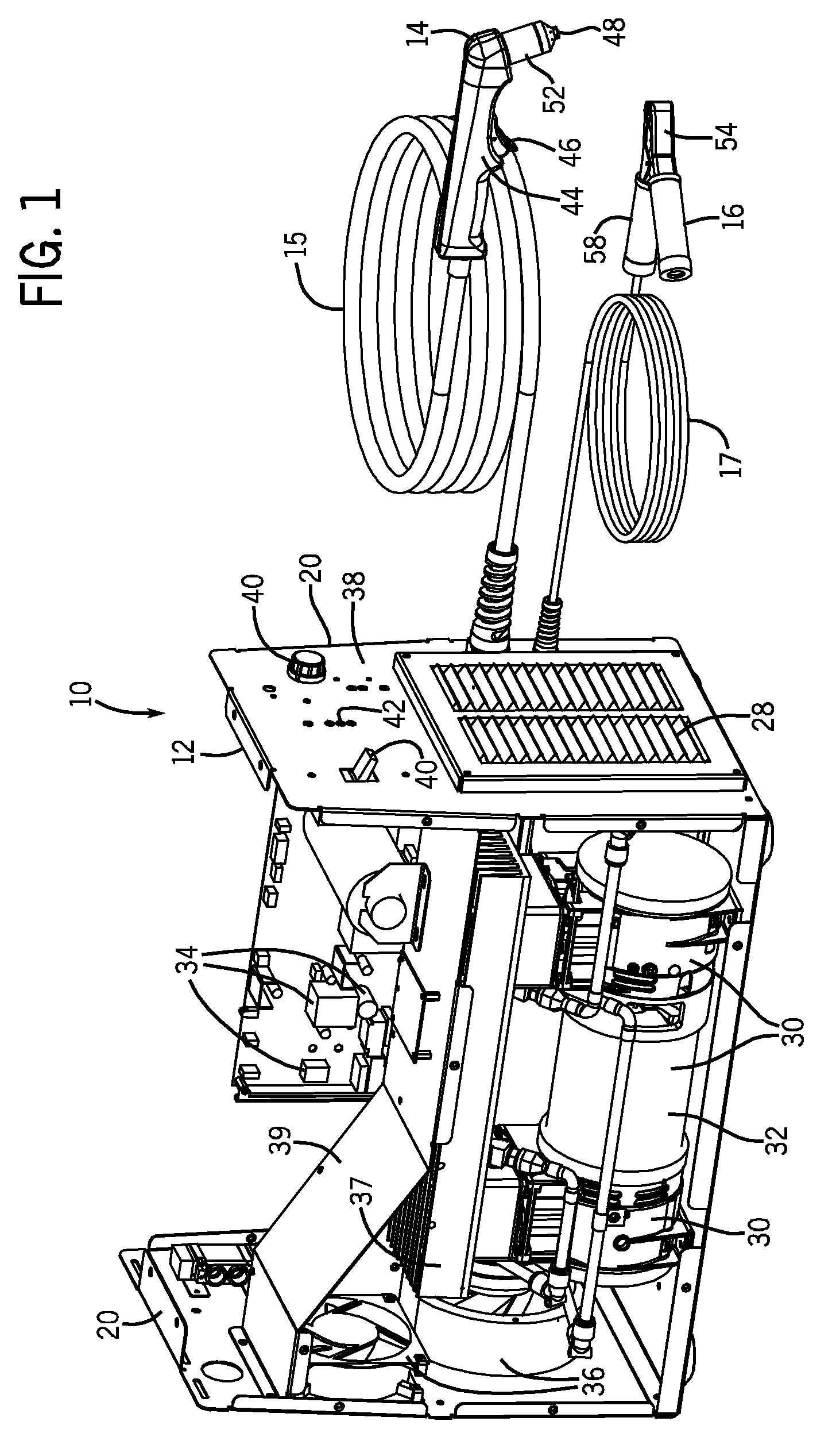
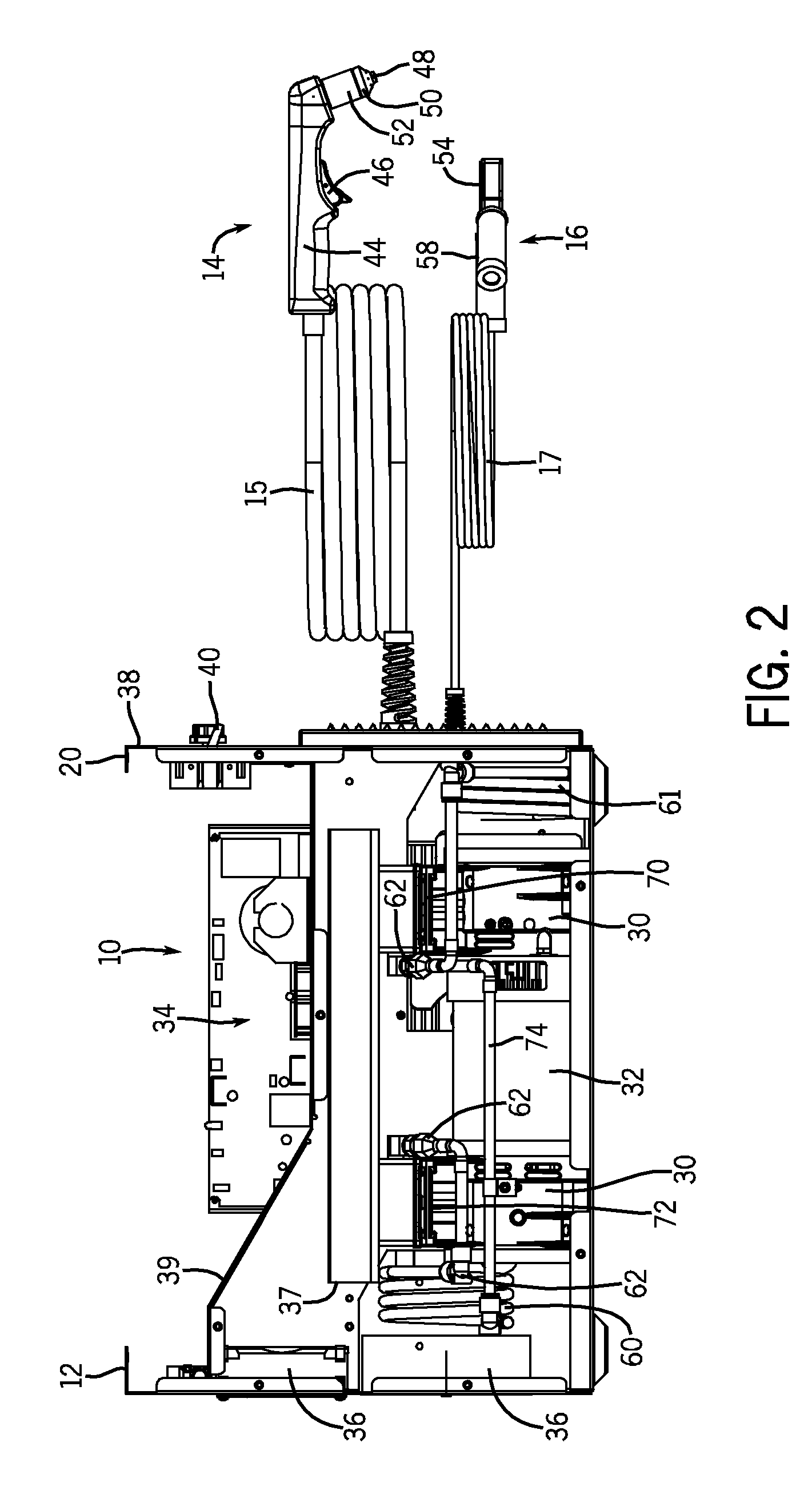
[0014]Referring now to the drawings, FIGS. 1 and 2 are partial perspective views illustrating an embodiment of a portable plasma cutting system 10 having a multi-stage (e.g., two-stage) compressor. Specifically, FIG. 1 illustrates the system 10 with an entire side panel assembly removed to provide a better view of the multi-stage compressor, whereas FIG. 2 illustrates a side view of the system 10 with compressor housings removed to better view components of the compressor. As discussed in further detail below, embodiments of the system 10 may include any welding type apparatus such as a plasma cutting system, welding system, induction heating system etc. that include a multi-stage compressor, such as a two-stage compressor, to provide compressed air to torches, other tools, or other components connected to or disposed in the system 10. A multi-stage compressor, such as a two-stage compressor, compresses a gas in two or more compressor chambers connected in series such that a first c...


PUM

PropertyMeasurementUnit
atmospheric pressureaaaaaaaaaa
poweraaaaaaaaaa

Abstract

Systems and methods are provided for a torch power system using a multi-stage compressor. In one embodiment, a system includes a torch power unit that includes a compressor having multiple compression stages. A method of operation is provided that includes compressing a gas via a multi-stage compressor in a torch power unit. A method of manufacturing a torch power unit is provided that includes providing a multi-stage compressor for a torch power unit and mounting the multi-stage compressor inside an enclosure of the torch power unit. Another system is provided that includes a plasma cutting circuit, a multi-stage compressor, a motor coupled to the compressor, and a compressor controller.

Description

CROSS REFERENCE TO RELATED APPLICATIONS[0001]This application claims priority to and the benefit of U.S. Provisional Application No. 61 / 015,175, entitled “Multi-Stage Compressor in a Plasma Cutter,” filed Dec. 19, 2007, the disclosure of which is incorporated herein by reference.BACKGROUND[0002]The invention relates generally to gas compressors, and more particularly to portable torch power systems utilizing an air compressor in a single unit.[0003]A variety of systems use compressed gas (e.g., compressed air). For example, compressed air may be used to power tools, such as wrenches, sanders, spray guns, and so forth. By further example, compressed gas (e.g. air) may be used with various torches, such as a plasma cutting torch. A plasma cutting system creates plasma (e.g., high temperature ionized gas) to cut metal or other electrically conductive material. In general, an electrical arc converts a gas (e.g., compressed air) into plasma, which is sufficiently hot to melt the work pie...

Claims


Application Information

Patent Timeline
Patent Type & Authority Patents(United States)
IPC IPC(8): B23K9/10H05H1/36
CPCH05H1/36B23K28/02B23K10/00Y10T29/49236
Inventor SOMMERFELD, TROY, A.
Owner ILLINOIS TOOL WORKS INC
Why Eureka
Try Eureka