Display control device, method, program, and integrated circuit

a control device and display technology, applied in repeater circuits, selective content distribution, instruments, etc., can solve the problems of increasing applications which do not provide sufficient comfort for users to operate in screen display apparatuses, and achieve the effect of ensuring comfort for users, increasing operability, and reducing additional costs

Active Publication Date: 2014-10-14
PANASONIC INTELLECTUAL PROPERTY CORP OF AMERICA
View PDF17 Cites 4 Cited by
  • Summary
  • Abstract
  • Description
  • Claims
  • Application Information

AI Technical Summary

Benefits of technology

[0067]The present invention allows the image or the like to be properly displayed on the screen according to the natural operation by the user on the operating device that is operated in various directions. As a result, the comfortable operability for the user is assured. Moreover, additional costs can be reduced by using an original function of the operating device, that is, input to a touchpad by the user. In other words, it is possible to achieve both increase in the operability for the user and reduction in the additional costs.

Problems solved by technology

As a result, applications have been increasing which do not provide sufficiently comfortable operability in screen display apparatuses having operating devices such as conventional remote-control devices (remote control).
However, PTL 3 indicates, as a problem in a method of checking, using only touch sensors, a direction of a device, a case where upper and lower directions of display may be reversed depending on a way the user holds the device.

Method used


Image

  • Display control device, method, program, and integrated circuit
  • Display control device, method, program, and integrated circuit
  • Display control device, method, program, and integrated circuit

Examples


embodiment 1

[0105]A screen display apparatus according to Embodiment 1 recognizes a direction (also referred to as an orientation) of an operating device including a touchpad, using a trajectory shape of plural position information items (coordinates) each indicating an input on the touchpad by a user. The screen display apparatus corrects display information of a cursor on a screen (a pointer indicating an operation position on a GUI) based on the direction of the operating device.

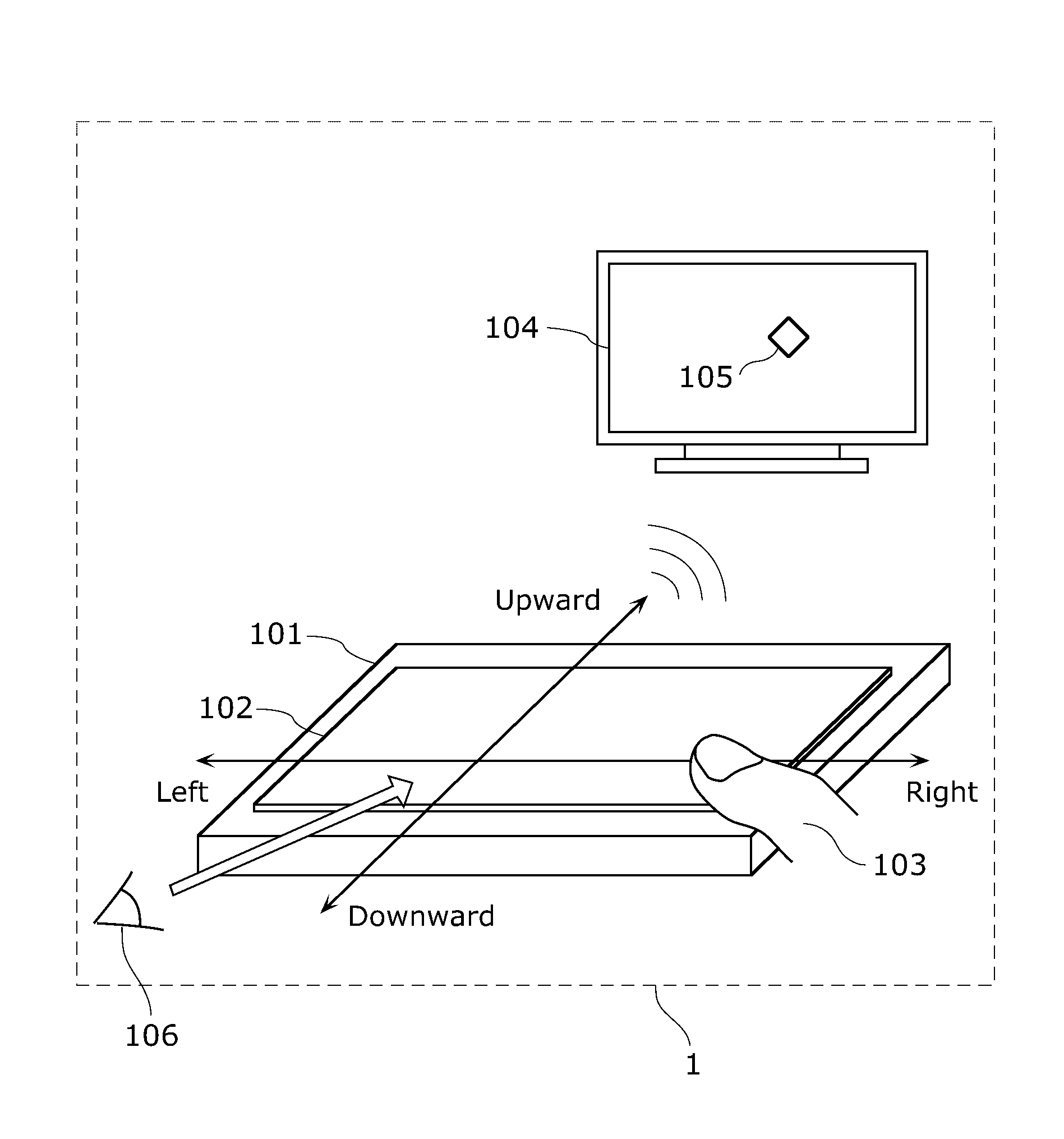
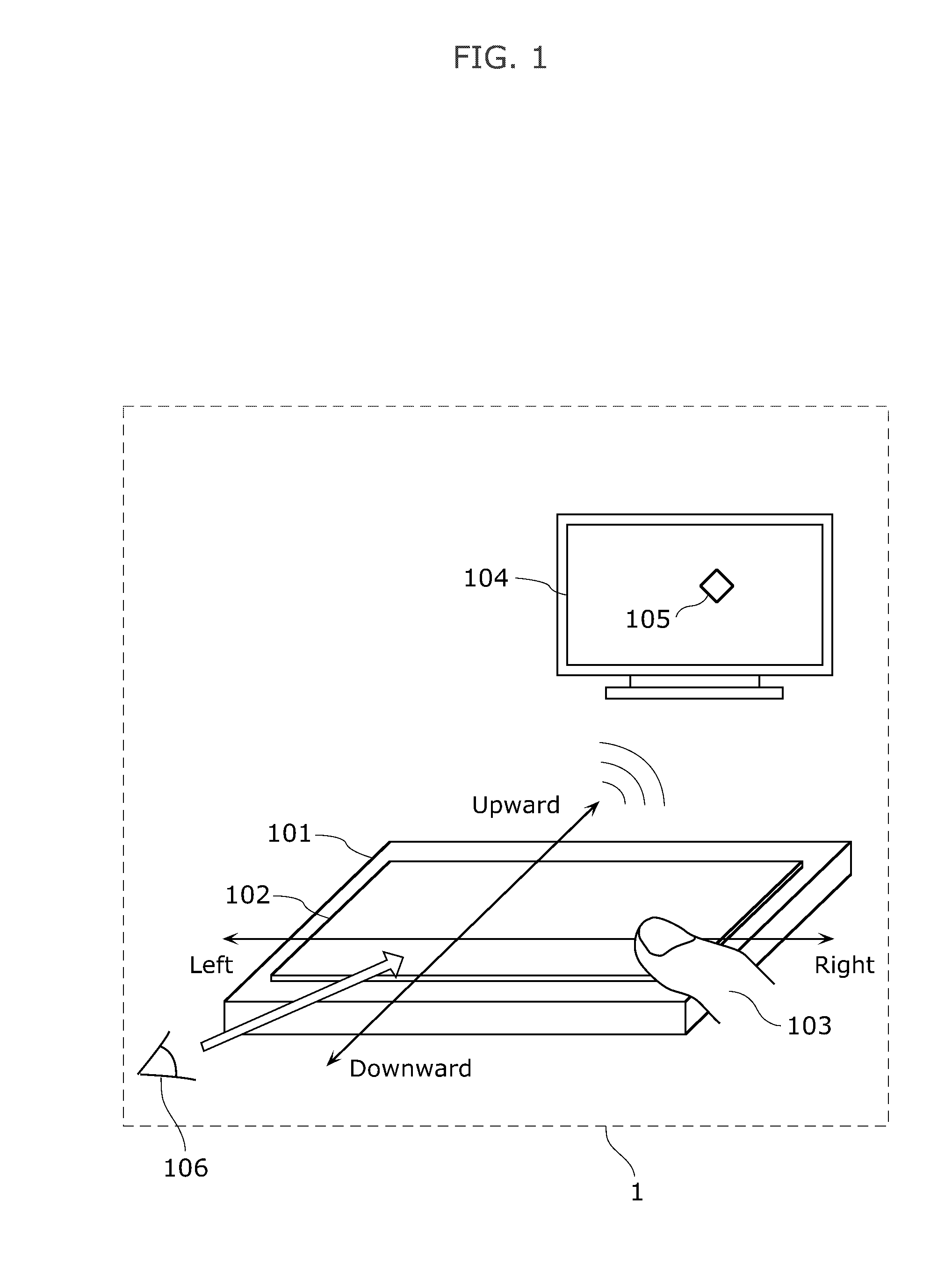
[0106]FIG. 1 is a schematic diagram of a screen display apparatus according to Embodiment 1. A screen display apparatus 1 shown in FIG. 1 receives an input from a user, and displays a cursor 105 or the like on a screen 104.

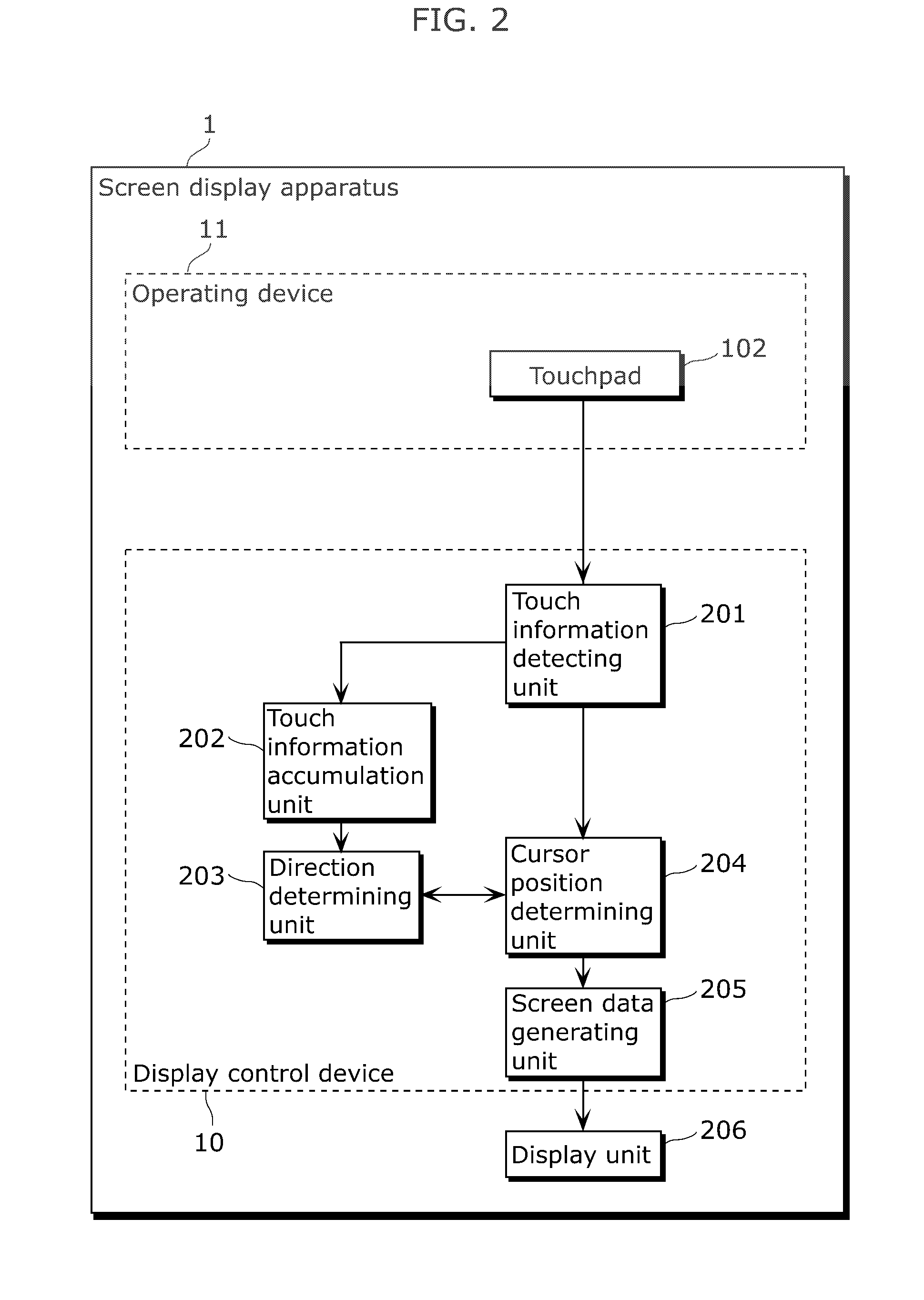
[0107]A remote control 101 is an example of an operating device with which the user operates a GUI on the screen 104. The remote control 101 includes a touchpad 102 which receives an input by a user's finger 103.

[0108]A method of detecting variation of capacitance or the like performs an input rece...

embodiment 2

[0208]A screen display apparatus according to Embodiment 2 includes two touchpads, and recognizes a direction of an operating device using an input on the two touchpads by a user. The screen display apparatus then corrects display positions of cursors on a screen based on the direction of the operating device.

[0209]FIG. 8 is a schematic diagram of a screen display apparatus according to Embodiment 2. A screen display apparatus 2 shown in FIG. 8 receives an input from a user, and displays cursors 806 or the like on a screen 805.

[0210]A remote control 801 is an example of the operating device with which the user operates a GUI on the screen 805. The remote control 801 includes a right touchpad 802 and a left touchpad 803 which receive an input by a user's finger 804.

[0211]A method of detecting variation of capacitance or the like performs an input receiving process by the right touchpad 802 and the left touchpad 803. The process is a publicly known technique, and thus a description th...

embodiment 3

[0304]A screen display apparatus according to Embodiment 3 which includes two touchpads further includes a sensor for detecting which part of an operating device a user holds.

[0305]This configuration allows the screen display apparatus according to Embodiment 3 to respond to a holding direction (hereafter, also referred to as “longitudinal holding”) of a remote control shown in FIG. 16, in addition to a holding direction (hereafter, also referred to as “lateral holding”) of the remote control according to Embodiment 2 shown in FIG. 8. The screen display apparatus according to Embodiment 3 recognizes a direction of the operating device in connection with one of the longitudinal holding and the lateral holding (the holding directions) using inputs on the touchpads of the screen display apparatus by the user, and corrects a display position of a cursor on a screen based on the holding direction and direction of the operating device.

[0306]FIG. 16 is a schematic diagram of a screen displ...


PUM


Abstract

The display control device is a display control device which receives a signal from the operating device having a touchpad and generates screen data to be displayed on a screen, the display control device including: a touch information detecting unit (201) which detects touch information including position information about a position on the touchpad that is touched with a finger of a user during operation of the touchpad; a direction determining unit (203) which determines a direction intended by the user, using a characteristic which is indicated by the touch information detected by the touch information detecting unit (201) and which results from the operation on the touchpad with the finger; and a screen data generating unit (205) which generates the screen data depending on the direction determined by the direction determining unit (203).

Description

TECHNICAL FIELD[0001]The present invention relates to a display control device which receives signals from an operating device having a touchpad a user operates with a user's finger, and generates screen data to be displayed on a screen.BACKGROUND ART[0002]In recent years, CE (Consumer Electronics) apparatuses such as digital TV (digital televisions) and BD (Blu-ray Disc) recorders have various functions thanks to compatibility with network and the like. As a result, applications have been increasing which do not provide sufficiently comfortable operability in screen display apparatuses having operating devices such as conventional remote-control devices (remote control).[0003]For instance, as an application used by a screen display apparatus, there is a web browser for browsing contents on the Internet. Furthermore, examples of such an application include a picture viewer for browsing, using a digital TV or a BD recorder, image data recorded on an SD (Secure Digital) card or the li...

Claims


Application Information

Patent Timeline
Patent Type & Authority Patents(United States)
IPC IPC(8): G06F3/041G06F3/033G06F3/0354G06F3/048G06F3/0481G06F3/0488H04N21/41H04N21/422
CPCG06F3/04883H04N21/4126H04N21/42204G06F3/03547H04N21/4104G06F3/041H04N21/4112H04N21/41265
Inventor HIGASHI, AKIOYAMAUCHI, MASAKIKOBAYASHI, SUSUMU
Owner PANASONIC INTELLECTUAL PROPERTY CORP OF AMERICA
Why Eureka
Try Eureka