Screw with low drilling resistance

a screw and low drilling technology, applied in the direction of screws, threaded fasteners, fastening means, etc., can solve the problems of adverse use and need to be modified, and achieve the effects of enhancing cutting efficiency, low drilling efficiency, and strengthening drilling competen

Active Publication Date: 2014-10-21
TAIWAN SHAN YIN INT CO LTD
View PDF5 Cites 15 Cited by
  • Summary
  • Abstract
  • Description
  • Claims
  • Application Information

AI Technical Summary

Benefits of technology

[0010]It is therefore the purpose of this invention to provide a screw with low drilling efficiency so as to enhance the cutting efficiency as well as reinforce the drilling competence, thereby achieving a speedy fastening effect.
[0011]The screw with low drilling resistance in accordance with the present invention comprises a head portion, a shank portion extended from the head, a plurality of first threads spiraling on the shank portion, and a drilling portion disposed on the shank, opposite to the head. Wherein, each first thread includes a first upper flank and a first lower flank connected to the first upper flank; a first included angle is converged by the first upper flank and the first lower flank. Characterized in that, a plurality of second threads are spiraled on the shank and are respectively disposed on the first upper flank and the first lower flank. Wherein, each second thread includes a second upper flank and a second lower flank connected to the second upper flank; a second included angle is converged by the second upper flank and the second lower flank. Concurrently, a plurality of opening slots are correspondingly defined on the second upper flank and the second lower flank. Further, the first included angle is smaller than the second included angle. Thereby, a favorably severing effect and accommodating manner could be provided. In addition to the disposition of the first threads between the second threads contributing to the reinforcement on the strength of the second threads whose second included angle is larger, the present invention achieves a low drilling resistance to speed up the fastening operation.

Problems solved by technology

Thus, the utilization is adversely limited, which indeed needs amendment.

Method used


Image

  • Screw with low drilling resistance
  • Screw with low drilling resistance
  • Screw with low drilling resistance

Examples


Embodiment Construction

[0026]Wherever possible, the same reference numbers are used in the drawings and the description to refer to the same or like parts.

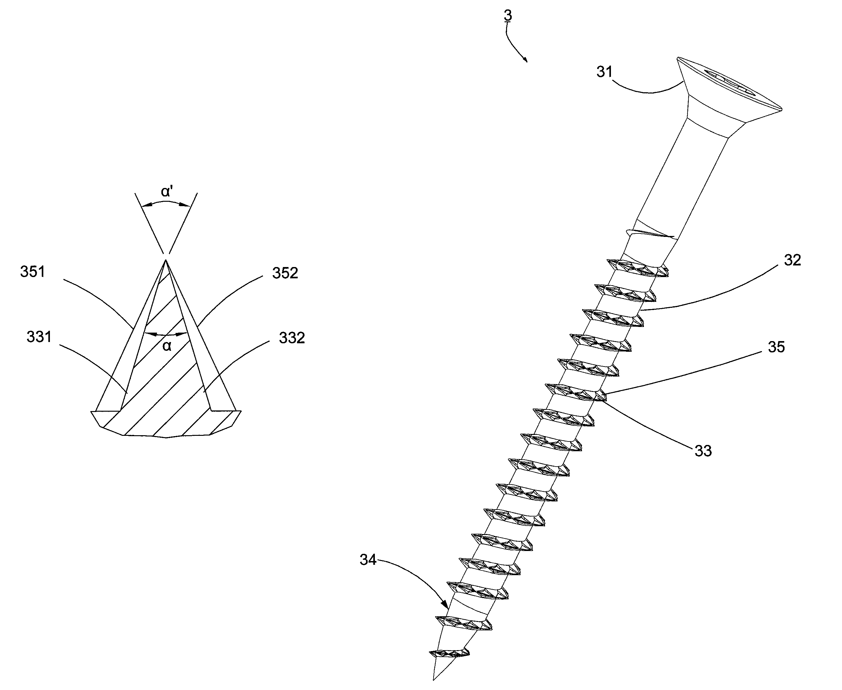
[0027]Referring to FIGS. 4 to 7, a first preferred embodiment of the present invention is shown. A screw 3 with low drilling resistance substantially comprises a head portion 31, a shank portion 32 extended from the head portion 31, a plurality of first threads 33 spiraling on the shank portion 32, and a drilling portion 34 disposed on the shank portion 32, opposite to the head portion 31. Wherein, each first thread 33 includes a first upper flank 331, and a first lower flank 332 connected to the first upper flank 331; a first included angle a is disposed at a convergence of the first upper flank 331 and the first lower flank 332. Characterized in that, a plurality of second threads 35 spiraling on the shank portion 32 is respectively disposed on the first upper flank 331 and the first lower flank 332. Wherein, each second thread 35 includes a second up...


PUM

PropertyMeasurementUnit
apex angleaaaaaaaaaa
drilling resistanceaaaaaaaaaa

Abstract

A screw with low drilling resistance comprises a head portion, a shank portion, a plurality of first threads, a drilling portion, and a plurality of second threads. Wherein, a plurality of opening slots are correspondingly defined on the second threads, and a first included angle of the first threads is smaller than a second included angle of the second threads. Thereby, the opening slots on the second threads efficiently provide the first threads with an auxiliary cutting effect and preferably offers a debris accommodating room. The first threads including the smaller first included angle favorably reinforce the bearing force of the second threads including the larger second included angle, thereby promoting the cutting effect of the screw and allowing a speedy screwing.

Description

BACKGROUND OF THE INVENTION[0001]1. Field of the Invention[0002]The present invention relates to a screw design, particularly to a screw with low drilling resistance for speeding up the drilling performance and enhancing the drilling force.[0003]2. Description of the Related Art[0004]Referring to FIGS. 1 to 3, a “Thread-Forming Screw Fastener”1 disclosed in the US Publication No. 2005 / 0186048 comprises a head portion 11, a shank portion 12 extended from the head 11, a plurality of threads 13 spiraling on the shank 12, and a drilling portion 14 disposed on the shank 12, opposite to the head 11. Wherein, a plurality of wave troughs 131 are defined on the threads 13. Especially, a first apex angle α included by an upper flank 132 and a lower flank 133 of the threads 13 is formed between 30°˜35°, and a second apex angle α′ included by wave crest 135 formed on the outer thread edge 134 of the deepest region of the wave troughs 131 is contoured between 30°˜58°. Further, a trough angle A i...

Claims


Application Information

Patent Timeline
Patent Type & Authority Patents(United States)
IPC IPC(8): F16B25/04F16B25/10F16B25/00
CPCF16B25/0015F16B25/0052F16B25/106
Inventor SU, GUO-CAI
Owner TAIWAN SHAN YIN INT CO LTD
Why Eureka
Try Eureka