
Tamper indicating closure assembly

a technology of closure assembly and indicating device, which is applied in the direction of tube connectors, intravenous devices, other medical devices, etc., can solve the problems of unused connectors, and achieve the effect of facilitating the addition of medicine and facilitating the dispensing of iv fluid

Active Publication Date: 2014-10-21
MEDICAL DEVICE ENG
View PDF55 Cites 35 Cited by
  • Summary
  • Abstract
  • Description
  • Claims
  • Application Information

AI Technical Summary

Benefits of technology

The present invention is a closure assembly specifically designed for female connectors, such as luer connectors, used in medical devices. The closure assembly is designed to indicate if there has been any tampering or attempted access to the connector. The closure assembly includes a housing with a hollow interior and a closed end portion, and an indicator member connected to the housing. The indicator member is fixed to the housing but can be easily removed to access the connector cover. The indicator member is connected to the housing with frangible members that detach when the housing is removed, leaving the indicator member on the connector cover as a clear indication of tampering. The closure assembly provides a reliable and effective solution for closing and sealing female connectors and alerting medical professionals of any tampering or attempted access.

Problems solved by technology

However, such an additional female luer connector may remain unused or may be accessed at a time subsequent to the initiation of the IV fluid administration, such as when additional medication or another composition is required or prescribed.

Method used


Image

  • Tamper indicating closure assembly
  • Tamper indicating closure assembly
  • Tamper indicating closure assembly

Examples


Embodiment Construction

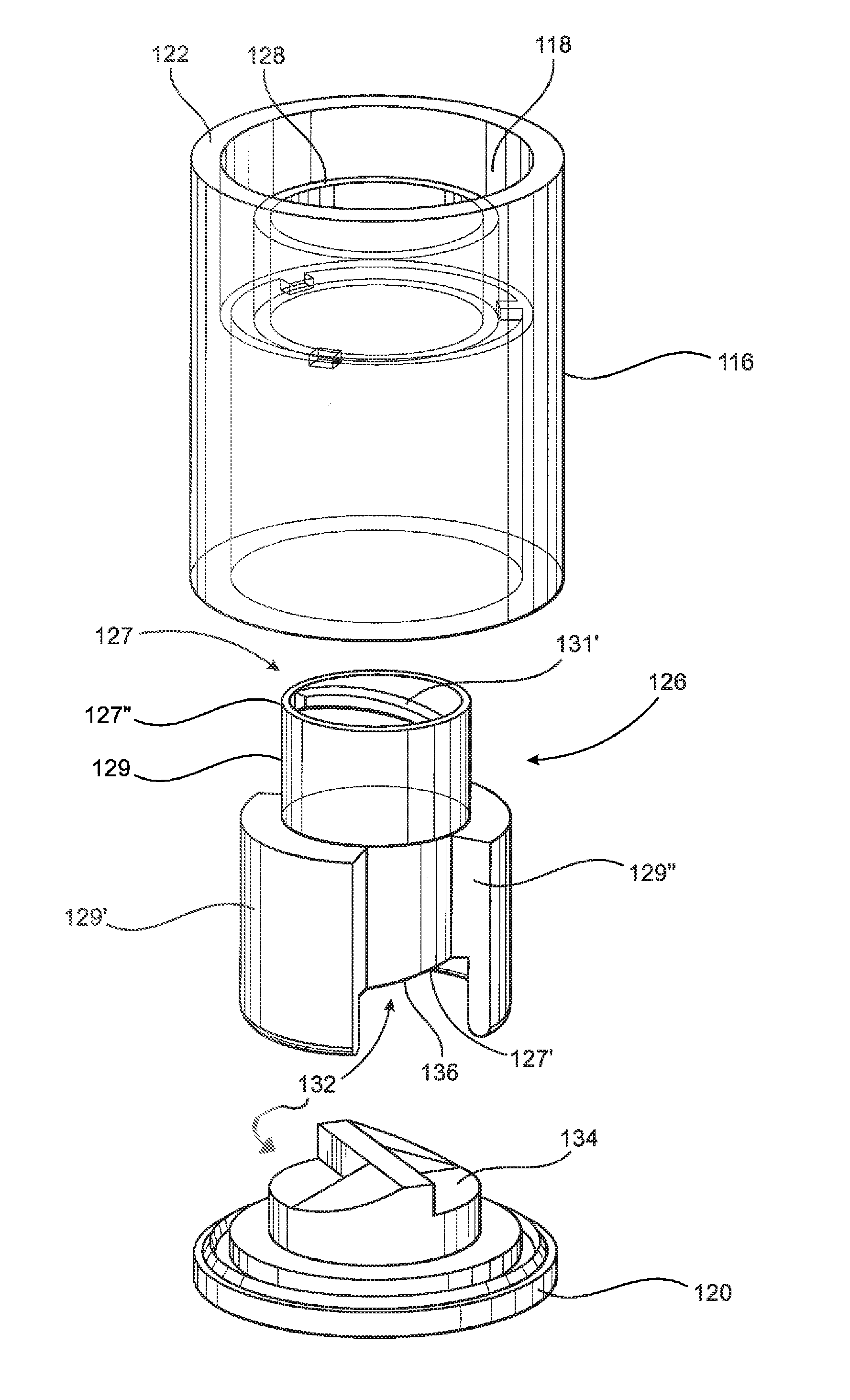
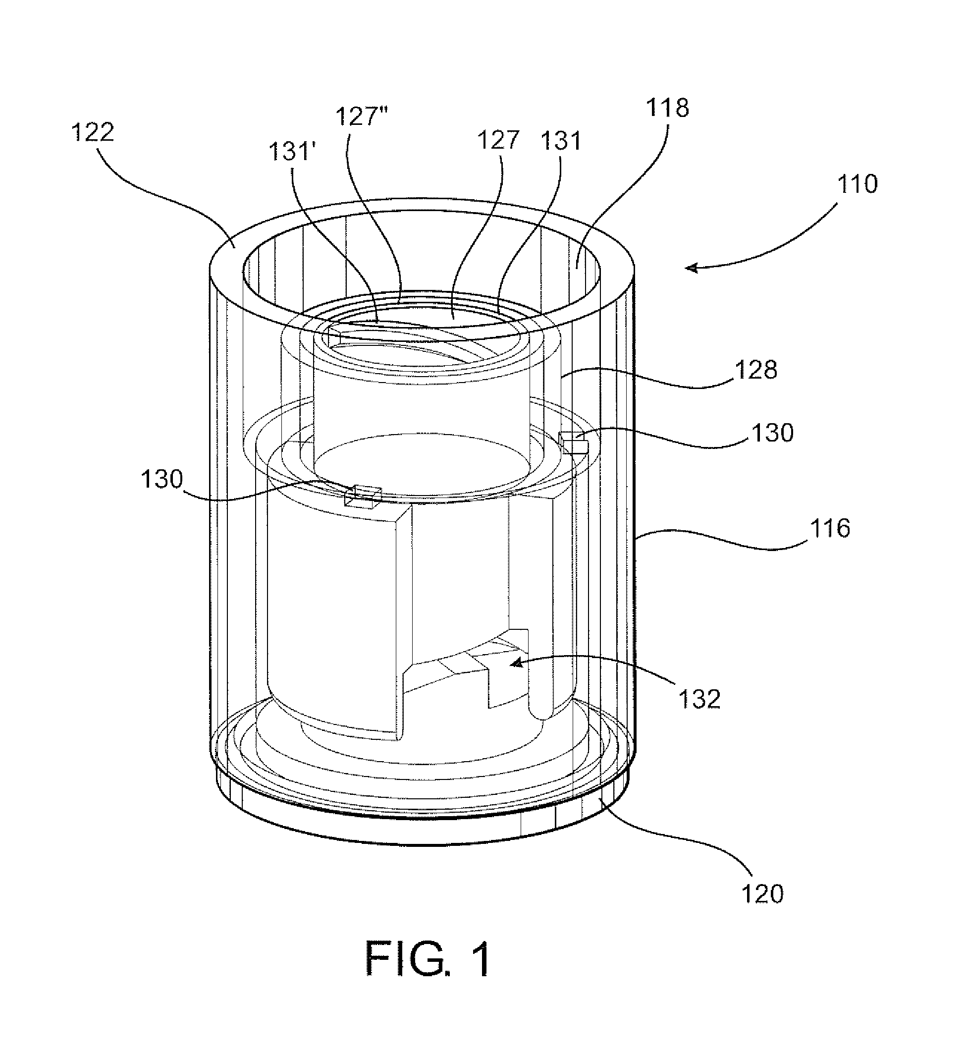
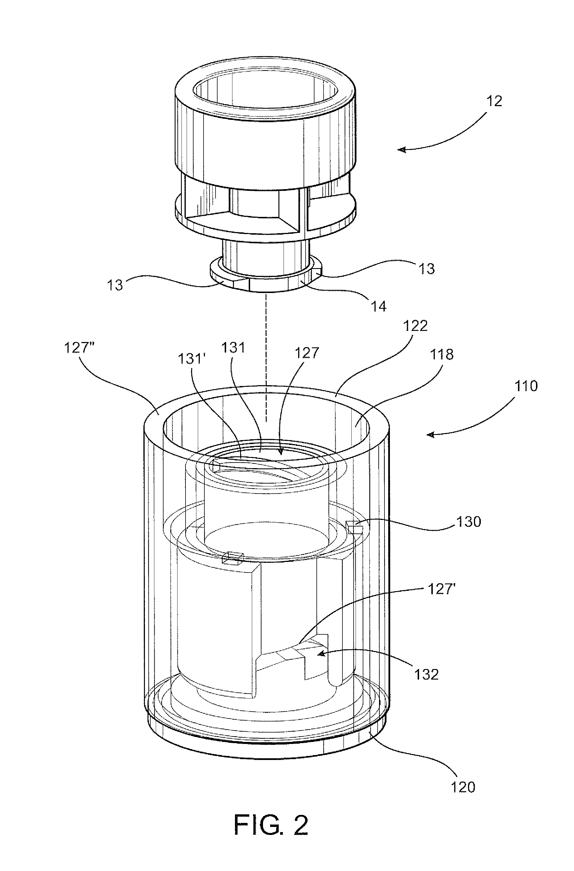
[0031]As represented in the accompanying drawings, the present invention is directed to a closure assembly, generally indicated as 110, which is preferably a tamper evident closure assembly. The closure assembly 110 is structured to enclose and will preferably provide a fluid seal with a female connector, generally indicated as 12, as is perhaps best shown in FIG. 2. In at least one preferred embodiment, the female connector 12 is more specifically defined and structured as a female luer connector including, as shown in FIG. 2, an interior port or access port 14 structured for the passage of fluid therethrough from a IV container or IV bag, or other reservoir with which the female luer connector 12 is associated. By way of example, a female luer connector or other female type connector may be connected to and / or directly associated with an intravenous (IV) dispensing assembly (not shown) of the type commonly used to administer fluid to a patient over a prescribed period of time, as ...


PUM


Abstract

A closure assembly structured for use with a female luer connector and operative to indicate an accomplished or attempted tampering thereof. A connector cover is movably and removably disposed within a housing and includes an interior chamber disposed and structured to receive an access port of the female connector. An indicator member is removably connected to an interior of the housing in surrounding relation to the connector cover and a drive assembly associated with both the connector cover and the housing is operable to concurrently rotate and axially advance the interior chamber into enclosing relation to the access port. Attempted removal of the housing from the female connector, such as by an applied axial force to the housing, will detach the indicated member from the housing and dispose it in a visually observable position surrounding the connector cover, thereby indicating attempted access.

Description

CLAIM OF PRIORITY[0001]The present Non-Provisional patent application claims priority pursuant to 35 U.S.C. Section 119(e) to prior filed Provisional patent application, namely, that having Ser. No. 61 / 419,508 filed on Dec. 3, 2010, as well as to another prior filed Provisional application, namely, that having Ser. No. 61 / 462,097 filed on Jan. 28, 2011, the contents of which are both incorporated herein by reference in their entireties.BACKGROUND OF THE INVENTION[0002]1. Field of the Invention[0003]This invention is directed to a closure assembly for use on a female luer connector or other generally similar connector of the type used with intravenous (IV) administration assemblies for the dispensing IV fluid and / or the adding of medicine or other agents to the IV container for dispensing. The closure assembly is structured to restrict unauthorized access to the female luer connector and further, to provide an obvious indication of attempted access to or other efforts to tamper with ...

Claims


Application Information

Patent Timeline
Patent Type & Authority Patents(United States)
IPC IPC(8): A61M5/00
CPCA61M39/10A61M5/5086A61M2039/1033A61M5/00A61M39/1011A61M39/20A61M2039/1083
Inventor VITELLO, JONATHAN
Owner MEDICAL DEVICE ENG
Learn More