Implant for bone fixation

a bone fixation and implant technology, applied in the field of implants, can solve the problems of bone plate slipping, bone plate slipping in an undesired direction, bone plate may lose the contact between the bone contacting surface of the plate and the bone, etc., to achieve high screw-plate-bone construct stability, stabilize the truss formed, and stabilize the truss

Active Publication Date: 2014-10-21
STRYKER EURO OPERATIONS HLDG LLC
View PDF23 Cites 55 Cited by
  • Summary
  • Abstract
  • Description
  • Claims
  • Application Information

AI Technical Summary

Benefits of technology

[0009]Aspects of the present disclosure are directed to facilitating a rapid healing of a bone fracture and guaranteeing a high screw-plate-bone construct stability.
[0034]According to a further aspect, there is provide a method for fracture fixation of bone comprising the steps of fixing an implant against bone with at least one bone fastener, wherein the implant comprises a shaft region having one or more holes for receiving bone fasteners, and a head region extending from the shaft region and having a plurality of circular holes for receiving bone fasteners, the plurality of circular holes including a central (threaded or unthreaded) screw hole having a center and at least three locking screw holes each having a center and surrounding the central screw hole, wherein the centers of the locking screw holes define a polygon and wherein the center of the central screw hole is located on or within the polygon; inserting a compression screw through the central screw hole of the implant into bone for compressing the fracture of bone; and inserting at least three locking screws or cortical screws into the locking screw holes of the implant for producing a locking engagement therebetween, thereby stabilizing the truss formed by the implant, the screws and bone.
[0036]Due to the fact that the center of the central screw hole is located on or within a polygon defined by the centers of the locking screw holes, the head portion has a defined hole configuration which guarantees a desired high screw-plate-bone construct stability. Therefore, the implant provides an optimal biomechanical stability and better resistance to pull out. Further, the implant cannot lose the contact to bone and cannot be shifted in an undesired direction. Thus, the medical success increases and rapid healing is achieved.

Problems solved by technology

In the vicinity of a compression screw, conventional bone plates cannot guarantee a desired screw-plate-bone construct stability, since compression screws cannot be locked to unthreaded plate holes.
Therefore, it is possible that the bone plate is shifted in an undesired direction or is pulled out.
Further, the bone plate may lose the contact between the bone contacting surface of the plate and the bone.
Thus, the medical success may decrease and rapid healing may not achieved.

Method used


Image

  • Implant for bone fixation
  • Implant for bone fixation
  • Implant for bone fixation

Examples


Embodiment Construction

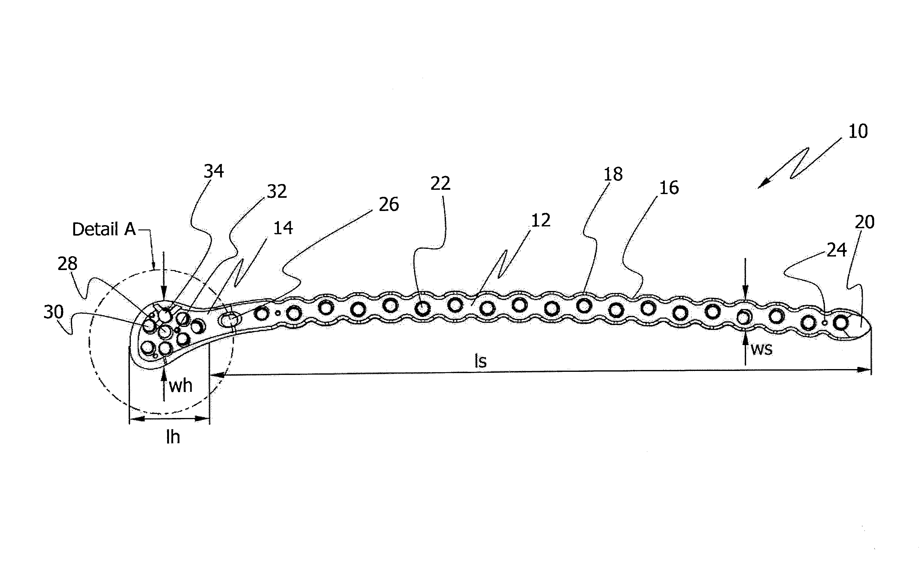
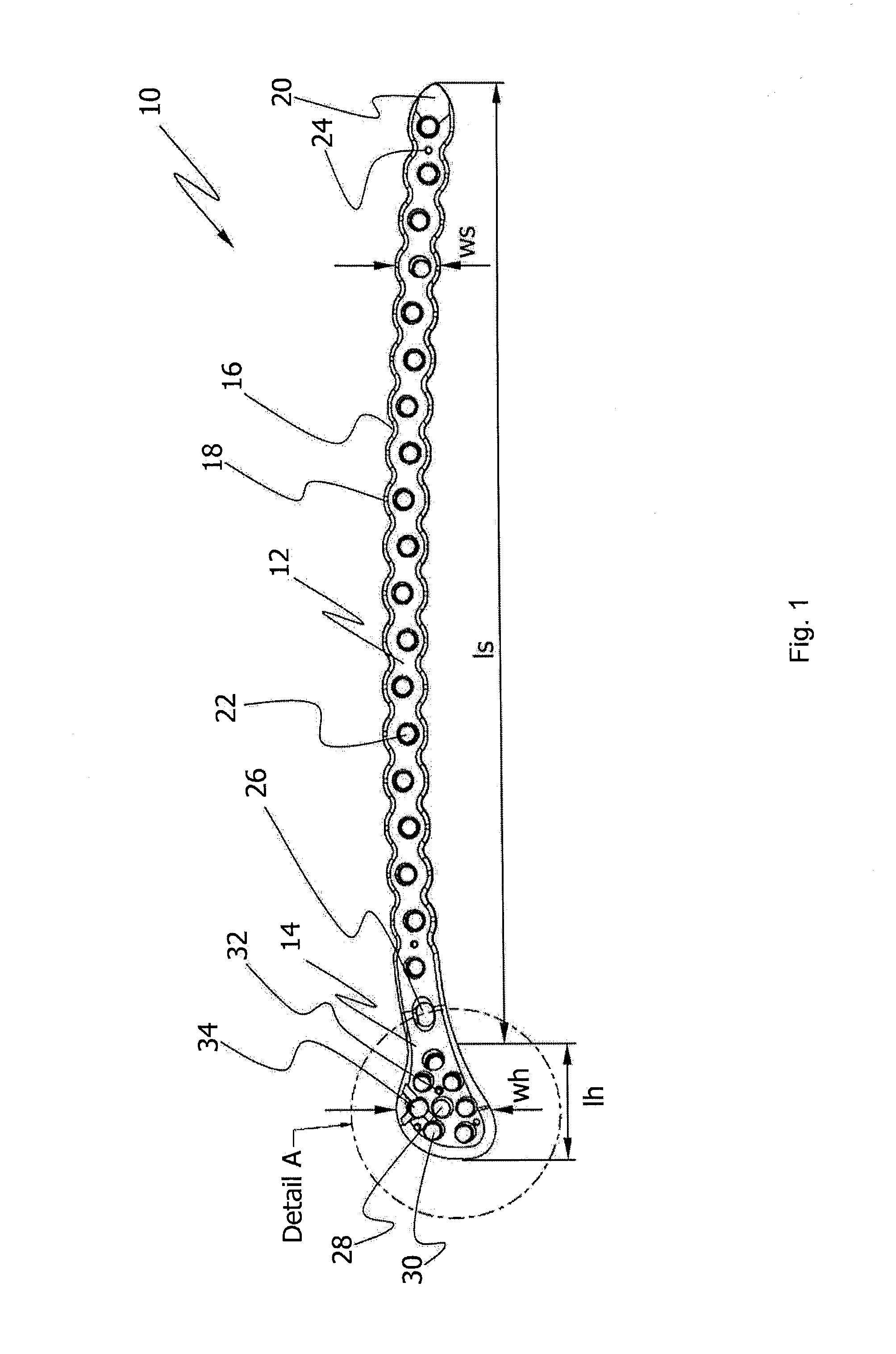
[0047]Referring to FIG. 1, there is shown a top view of a first embodiment of an implant in form of a bone plate 10 for use in orthopedic surgery for fixation of bone (not shown in FIG. 1). The bone plate 10 has a length of approximately 380 mm and a width of approximately 40 mm. As shown in FIG. 1, the width of bone plate 10 varies over the entire length of the bone plate 10. Further, the bone plate 10 has a maximum thickness of approximately 5 mm. Also the thickness of the bone plate can vary over the entire length of bone plate 10. For facilitating the arrangement of bone plate 10 within a patient's body, the bone plate 10 includes a portion along the outer peripheral side thereof which may be angled.

[0048]The bone plate 10 is made of a biocompatible material such as stainless steel, titanium or a titanium alloy, and comprises a shaft region 12 and a head region 14 extending from the shaft region 12. The shaft region 12 is shaped to conform to an extra-articular part of a bone su...


PUM


Abstract

An implant for use in orthopedic surgery for fixation of bone has a shaft region and a head region, both including a plurality of holes for receiving bone fasteners. The head region of the implant has a central screw hole and threaded surrounding screw holes surrounding the central screw hole in a defined configuration.

Description

CROSS-REFERENCE TO RELATED APPLICATION[0001]This application claims the benefit of European Patent Application No. 10005423.8 filed May 25, 2010, the disclosure of which is hereby incorporated herein by reference.BACKGROUND OF THE INVENTION[0002]The present disclosure generally relates to an implant such as a bone plate for use in orthopedic surgery, preferably for fixation of bone. The disclosure further relates to an implant system and a method for fracture fixation of bone.[0003]Bone plates may be employed for treating periarticular and / or intra-articular fractures of, for example, the proximal humerus, distal femur, proximal tibia or the distal tibia. Such bone plates are available in a plurality of variations for different applications and can have an I-, T-, L-, cloverleaf- or calcaneal-shape.[0004]Bone plates for periarticular and other fractures can include threaded and unthreaded holes to receive locking and non-locking screws, respectively. The locking screws can be secure...

Claims


Application Information

Patent Timeline
Patent Type & Authority Patents(United States)
IPC IPC(8): A61B17/80
CPCA61B17/8061A61B17/8057
Inventor SCHWAGER, MANUELSYLVESTRE, PIERRE-LUCWIDER, ROBERT
Owner STRYKER EURO OPERATIONS HLDG LLC
Why Eureka
Try Eureka