Fluidized bed system

a bed system and flue gas technology, applied in the direction of granular delivery, granulation in stationary drums/troughs, granulation by powder suspension, etc., can solve the problems of increased compaction in the extruder, unfavorable fully automated, continuous or semi-continuous parallel operation of these systems, and the modification of granule properties

Active Publication Date: 2021-09-07
HUETTLIN GMBH
View PDF16 Cites 0 Cited by
  • Summary
  • Abstract
  • Description
  • Claims
  • Application Information

AI Technical Summary

Benefits of technology

[0008]Furthermore, provision is preferably made for the fluidized bed installation to have an outlet line. The outlet line connects all the outlets of all the granulation units. Provision is in turn preferably made for the granulation units to be arranged in a ring, such that the outlet line is a ring line. The arrangement may alternatively also be linear, such that the outlet line likewise extends in a linear manner. Each outlet is advantageously connected to the outlet line via its own valve, such that individual granulation units may optionally be emptied. The outlet line is also advantageously connected with a waste collection device. In this way, excess material can be collected and preferably disposed of via the waste collection device. The waste collection device may be the same waste collection device as previously described. Provision is particularly advantageously made, both for the inlet line and for the outlet line, for said lines to be annular, wherein the lines may also have other shapes, in particular they may extend in a linear manner. In this respect, the inlet line and / or the outlet line may also take the form of ring segments. In a further particularly preferred embodiment, the granulation units are arranged in an annular manner, wherein the inlet line at least in part encloses the granulation units from outside while the outlet line, at least in the form of a ring segment, is arranged inside the annularly arranged granulation units. This ensures a highly space-saving construction. A linear arrangement of the granulation units provides good accessibility for each individual granulation unit within the fluidized bed installation. Simple manual cleanability may thus in particular also be achieved.
[0009]In one advantageous embodiment, the fluidized bed installation comprises a cleaning module. The cleaning module is operatively connected with each granulation unit. An annular or ring segment-shaped cleaning line is particularly advantageously present, which connects the fluidized bed tanks of all the granulation units. Each granulation unit may thus be cleaned by the cleaning module. Provision is in turn particularly advantageously made for valves to be present to connect each fluidized bed tank with the cleaning line. It is thus ensured that cleaning of one granulation unit may proceed independently of other granulation units. This in particular also makes it possible for one granulation unit to be cleaned while other granulation units continue to operate.
[0011]The fluidized bed installation preferably comprises at least one module inlet. The module inlet is connected with the inlets of all the granulation units. The above-described inlet line is particularly advantageously present, such that the module inlet is connected with the inlet line. The module inlet is drivable by the control unit. Thus, the control unit is a centralized entity not only for driving the individual granulation units, but also for driving the module inlet. The granulation process may thus take place safely and reliably within the granulation units, since all the preparatory work parameters are known.
[0015]The invention additionally relates to a method for semi-continuous production, in particular of pharmaceutical granules within a fluidized bed installation. In this case, provision is made for individual granulation units of the fluidized bed installation to be individually and / or mutually independently operable. Moreover, provision is preferably made for the individual granulation units to be cleanable independently of operation of the other granulation units. This allows fluidized bed installations to operate without interruption.

Problems solved by technology

A disadvantage of such systems is the modified granule properties resulting from the greater compaction in the extruder.
However, satisfactory, fully automated, continuous or semicontinuous parallel operation of these systems has not hitherto been possible.
In particular, no solution is known or accepted in pharmaceutical production which ensures continuous granulation in such a system and automated or partially automated intermediate cleaning of individual granulation units.
However, these systems are not accepted either in the pharmaceutical industry or by the licensing authorities.
In addition, the pharmaceutical industry has not hitherto offered suitable process control or integration of higher-level overall control of the fluidized bed granulation installation into an entire production line, or the possibility of continuous or semicontinuous granulation and coating in parallel operation.

Method used


Image

  • Fluidized bed system
  • Fluidized bed system
  • Fluidized bed system

Examples


Embodiment Construction

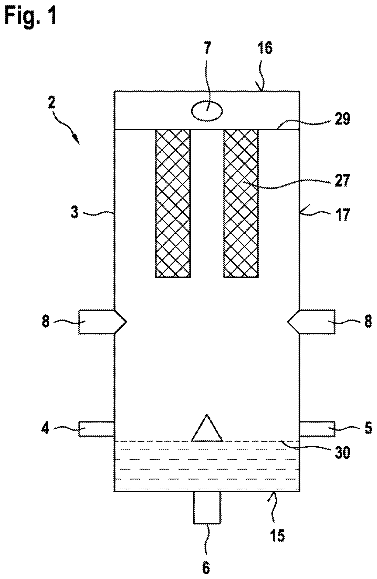
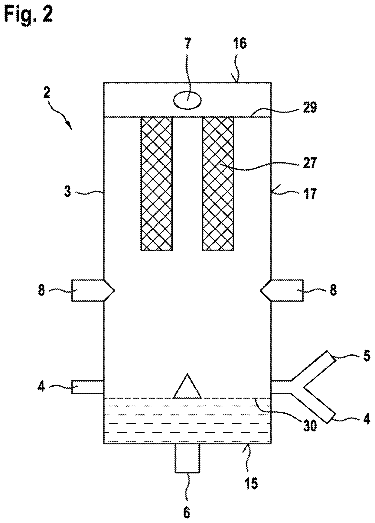
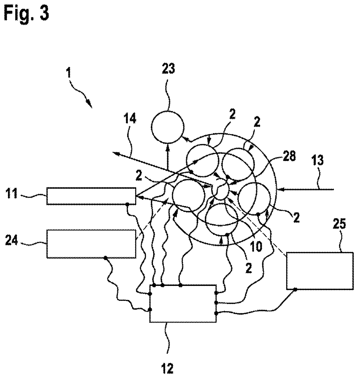
[0028]FIG. 1 shows a granulation unit 2 of a fluidized bed installation 1 (cf. FIGS. 2 and 3) according to one exemplary embodiment of the invention. A fluid, in particular a gas, particularly preferably air, is fed to the granulation unit 2 via an air treatment installation, not shown, with heat exchanger, filter and external air supply. Gas is fed into the granulation unit 2 via a fluid inflow 6, wherein the fluid inflow 6 is arranged in a bottom 15 of the granulation unit 2. A disk-shaped gas distributor plate 30 is in particular arranged above the bottom 15, which plate distributes the supplied air over a large area across the entire cross-section of the fluidized bed tank 3.

[0029]The bottom 15 is in particular is of circular construction and delimits a hollow-cylindrical fluidized bed tank 3. Moreover, the fluidized bed tank 3 is delimited by a likewise circular lid 16. Thus, side walls 17 of the fluidized bed tank 3 extend between the bottom 15 and the lid 16. The bottom 15 an...


PUM

PropertyMeasurementUnit
temperatureaaaaaaaaaa
pressureaaaaaaaaaa
shapesaaaaaaaaaa

Abstract

The invention relates to a fluidised bed system (1) comprising a plurality of granulation units (2), arranged so as to be functionally parallel, for producing pharmaceutical granules, each granulation unit (2) comprising: a fluidised bed container (3), an inlet (4) and an outlet (5) on said fluidised bed container (3), a fluid supply (6) and a fluid discharge (7) on said fluidised bed container (3), and at least one injection nozzle (8) for injecting a processing substance into the fluidised bed container (3), as well as a control unit for adjusting processing conditions within each granulation unit (2).

Description

BACKGROUND OF THE INVENTION[0001]The invention relates to a fluidized bed system or installation. In particular, the invention relates to a fluidized bed granulation installation. The fluidized bed installation or the fluidized bed granulation installation are suitable in particular for processing pharmaceutical powders.[0002]The processing of pharmaceutical powders in a fluidized bed is known from the prior art. This includes in particular the processes of drying, coating and granulation. At present, systems with extruder and downstream fluidized bed dryers are preferably used for continuously operated pharmaceutical wet granulation units. A disadvantage of such systems is the modified granule properties resulting from the greater compaction in the extruder. Wet granulation of pharmaceutical powders in the fluidized bed installation is known from batch-operated systems. However, satisfactory, fully automated, continuous or semicontinuous parallel operation of these systems has not ...

Claims


Application Information

Patent Timeline
Patent Type & Authority Patents(United States)
IPC IPC(8): B01J2/10B01J2/16A61K9/16
CPCB01J2/16A61K9/1682
Inventor WOLPENSINGER, BERNDPAASCHE, CHRISTIAN KARLMICHAELIS, MARCBOERNER, MATTHIASZERRER, NORBERT
Owner HUETTLIN GMBH
Why Eureka
Try Eureka