Check patentability & draft patents in minutes with Patsnap Eureka AI!

Vehicular power transmission device

a transmission device and vehicle technology, applied in the direction of engine-driven generators, transportation and packaging, transportation, etc., can solve the problem of not being able to select the efficient operating conditions of the engine and the electric motor individually

Inactive Publication Date: 2014-10-28
DENSO CORP
View PDF16 Cites 6 Cited by
  • Summary
  • Abstract
  • Description
  • Claims
  • Application Information

AI Technical Summary

Benefits of technology

[0016]With such the construction, slowing down, direct coupling and speeding up of the rotation speed of the engine are possible. As for the motor, direct coupling and slowing down can be performed.

Problems solved by technology

Therefore, it is impossible to select efficient operating conditions of the engine and the electric motor individually.

Method used


Image

  • Vehicular power transmission device
  • Vehicular power transmission device
  • Vehicular power transmission device

Examples


Embodiment Construction

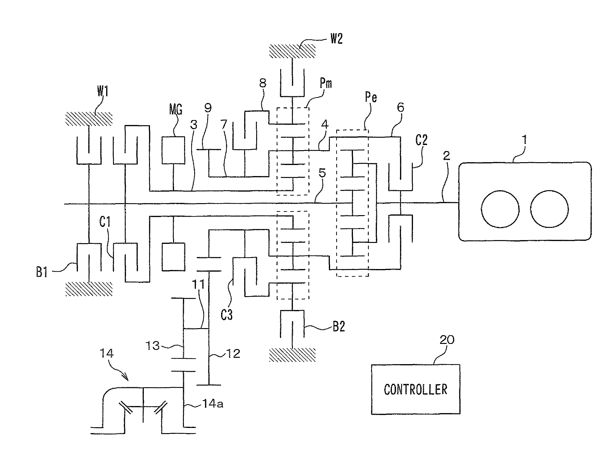
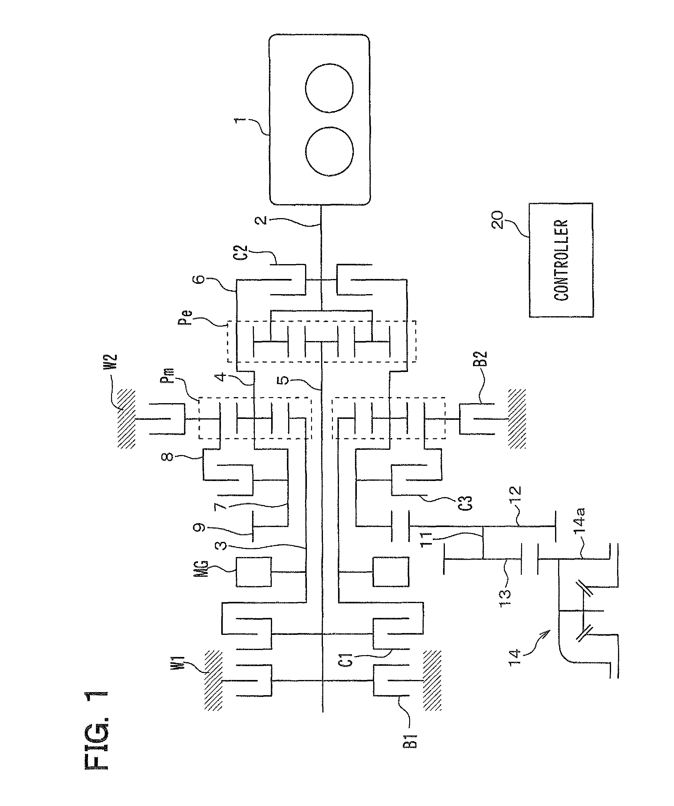
[0030]Hereinafter, an embodiment of the present invention will be described. FIG. 1 is a skeleton diagram showing a construction of a vehicular power transmission device according to the present embodiment. The vehicular power transmission device has an engine 1, which is an internal combustion engine, and a motor MG driven with an electric power of a battery, which is a secondary battery, as power generation devices for generating power for running a hybrid vehicle.

[0031]Further, the vehicular power transmission device has a first planetary gear mechanism Pe, to which the power generated by the engine 1 is inputted, and a second planetary gear mechanism Pm, to which the power generated by the motor MG is inputted. Each of the first planetary gear mechanism Pe and the second planetary gear mechanism Pm is a well-known gear mechanism having three well-known rotation members of a sun gear, a carrier and a ring gear.

[0032]In the first planetary gear mechanism Pe, the carrier correspond...


PUM


Abstract

Power generated by an engine is inputted to a carrier of a first planetary gear mechanism. Power generated by a motor is inputted to a sun gear of a second planetary gear mechanism. Power from a ring gear of the first planetary gear mechanism and power from a carrier of the second planetary gear mechanism are combined and transmitted to an axle of driving wheels. While power input from the engine to the carrier of the first planetary gear mechanism is maintained, rotation of a sun gear of the first planetary gear mechanism is restricted with a first clutch, a second clutch or a first brake. While power input from the motor to the sun gear of the second planetary gear mechanism is maintained, rotation of a ring gear of the second planetary gear mechanism is restricted with a second brake or a third clutch.

Description

CROSS REFERENCE TO RELATED APPLICATION[0001]This application is based on and incorporates herein by reference Japanese Patent Application No. 2010-171882 filed on Jul. 30, 2010.BACKGROUND OF THE INVENTION[0002]1. Field of the Invention[0003]The present invention relates to a power transmission device for a vehicle.[0004]2. Description of Related Art[0005]Patent document 1 (JP-A-2009-1234) describes a technology for controlling a reduction gear ratio of an engine and a reduction gear ratio of an electric motor by using a planetary gear mechanism as a technology of a power transmission device of a hybrid vehicle.[0006]According to the technology of Patent document 1, a correspondence relationship between the reduction gear ratio of the engine and the reduction gear ratio of the electric motor is fixed. That is, if the reduction gear ratio of the engine is decided, the reduction gear ratio of the electric motor is also decided to be unique. Therefore, it is impossible to select efficie...

Claims


Application Information

Patent Timeline
Patent Type & Authority Patents(United States)
IPC IPC(8): F16H3/54B60K6/48B60K6/365F16H3/72B60L50/16
CPCF16H3/54Y02T10/7258F16H3/725Y02T10/6221B60K6/365B60K6/48B60K2006/4816Y02T10/6256B60K2006/4841Y02T10/62Y02T10/72
Inventor IMAMURA, TOMONORIKOSHIMOTO, SHINICHIROUOKADA, HIROSHI
Owner DENSO CORP
Features
  • R&D
  • Intellectual Property
  • Life Sciences
  • Materials
  • Tech Scout
  • Unparalleled Data Quality
  • Higher Quality Content
  • 60% Fewer Hallucinations
Learn More