Dust collector for a vacuum cleaner having a dust removal function

a technology of dust collector and vacuum cleaner, which is applied in the direction of cleaning filter means, separation processes, etc., can solve the problems of increasing the height of the whole dust collector, reducing the efficiency of picking up foreign objects from the cleaning surface or separating dust inside the centrifugal, and unable to effectively remove dust accumulated on the filter. , to achieve the effect of facilitating assembly and managemen

Active Publication Date: 2014-10-28
SAMSUNG ELECTRONICS CO LTD
View PDF11 Cites 14 Cited by
  • Summary
  • Abstract
  • Description
  • Claims
  • Application Information

AI Technical Summary

Benefits of technology

[0012]The present disclosure has been developed in order to overcome the above drawbacks and other problems associated with the above described prior arts. An aspect of the present disclosure is to provide a dust collector for a vacuum cleaner having a dust removal function, wherein the total volume of the dust collector does not increase and the efficiency in removing dust collected on a filter is improved.
[0013]Further, another aspect of the present disclosure is to provide a dust collector for a vacuum cleaner having a dust removal function which improves the efficiency in removing dust from the entire filter.
[0014]Further, another aspect of the present disclosure is to provide a dust collector for a vacuum cleaner having a dust removal function which reduces pressure loss and improves structures.
[0026]According to the aspects of the present disclosure, there is an advantage in that the dust collector providing the function of dislodging dust is minimized not to increase in size by arranging the dust removal unit and the drive unit on the same plane.
[0027]Also, there is an advantage in that the dust removal unit and the drive unit are arranged not to overlap with each other on the same plane and this leads to facilitating assembly and management of the dust removal unit and the drive unit, and accordingly facilitating assembly and management of the dust collector.
[0028]Also, there is an advantage in that the contact area of the dust removal unit and the filter member increases and impact is sent to the entire filter so that dust accumulated on the whole area of the filter can be removed evenly.

Problems solved by technology

The conventional dust collector may generally have deteriorated suction force as the secondary filter has fine dust gradually accumulated thereon, and subsequently decreased efficiency of picking up foreign matters from a cleaning surface or separating dust inside the centrifugal separator.
However, prior art 1 presents a problem in that since a driving unit is arranged to overlap with a driven unit, a combination structure is wide, and in case of a dust collector having a vertical structure, this results in increasing a height of the whole dust collector.
Further, said prior arts 1 and 2 present a problem in that as configurations of impacting on a filter using the projections formed on both sides of the driven unit (prior art 1) and the elastic member of grid structure (prior art 2), since a contact area is small between the projections formed on the driven unit or the elastic member for dislodging dust and the filter, vibration is not sent to the entire filter, and thus dust accumulated on the filter is not removed effectively.
Another problem lies in that dust is not removed evenly from the entire filter.

Method used


Image

  • Dust collector for a vacuum cleaner having a dust removal function
  • Dust collector for a vacuum cleaner having a dust removal function
  • Dust collector for a vacuum cleaner having a dust removal function

Examples


Embodiment Construction

[0035]Hereinafter, exemplary embodiments of the present disclosure will be described in further detail with reference to the accompanying drawings.

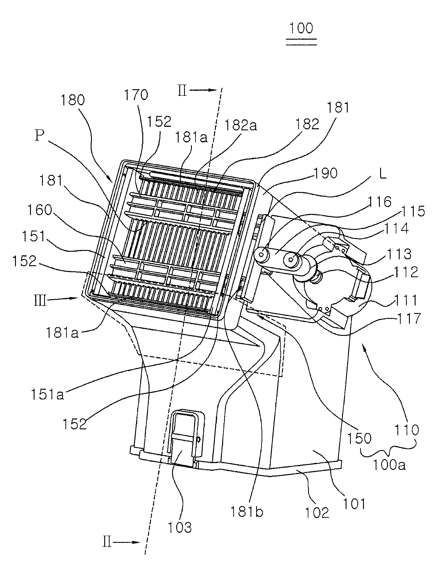
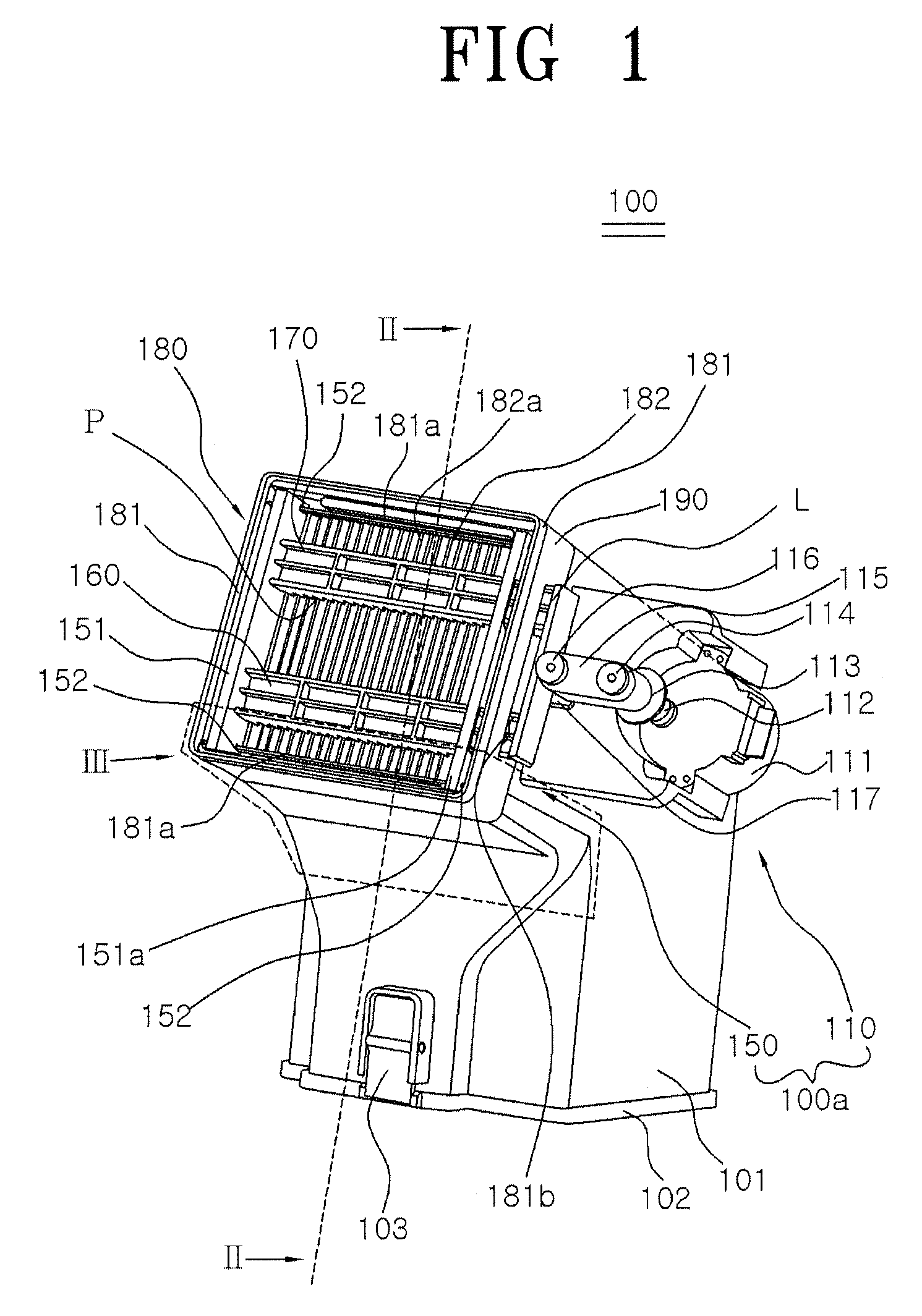
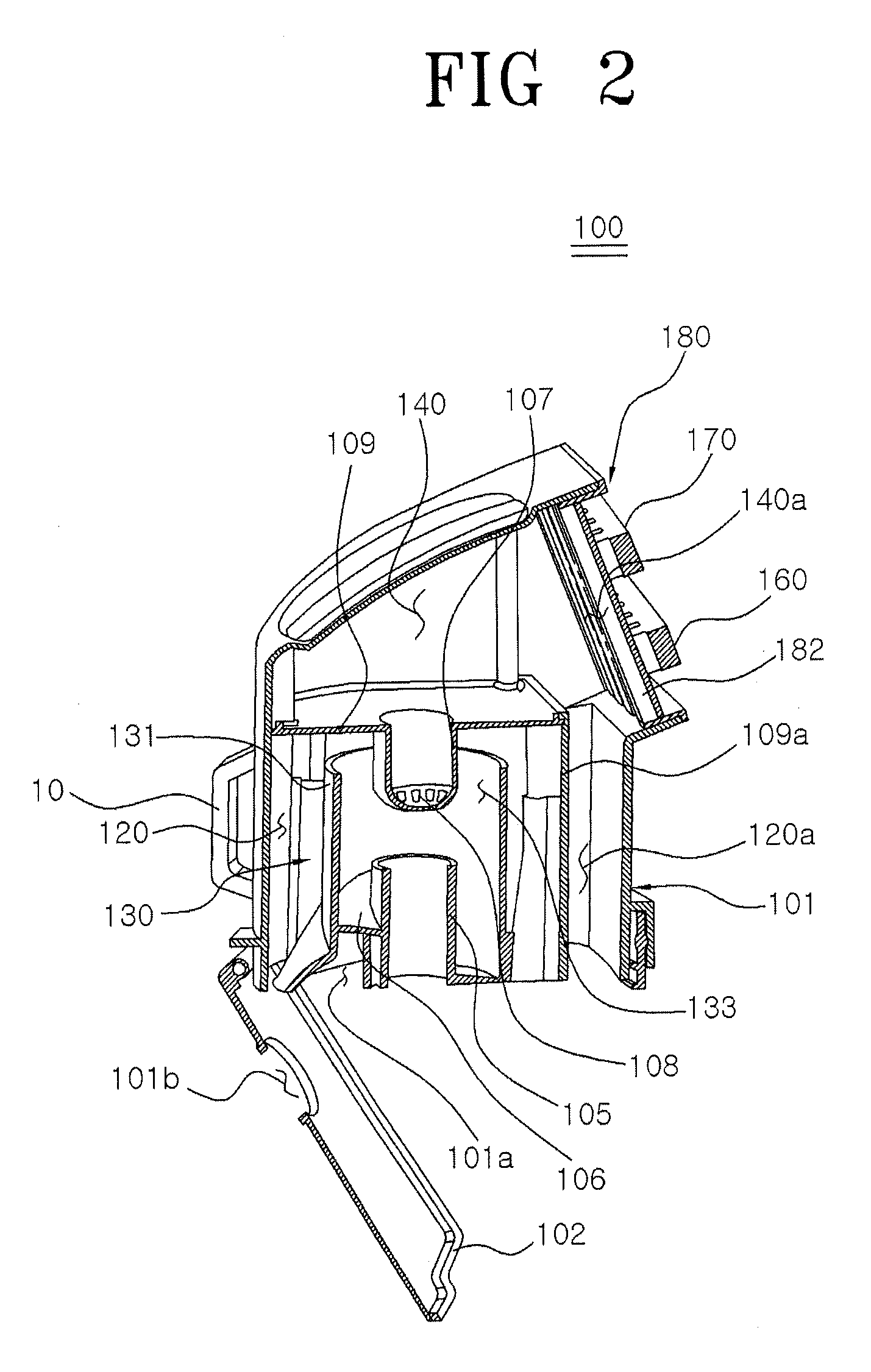
[0036]FIG. 1 is a perspective view illustrating a dust collector 100 according to a first exemplary embodiment of the present disclosure, FIG. 2 is a partial section view illustrating a dust collector 100 cut along line II-II shown in FIG. 1, and FIGS. 3 and 4 are partially exploded perspective views illustrating a dust collector 100 cut portion III shown in FIG. 1 so as to show a back and forth movement of a first dust-removing member 160 and a second dust-removing member 170.

[0037]Referring to FIGS. 1 to 4, the dust collector 100 according to the first exemplary embodiment of the present disclosure includes a dust container 101, a centrifugal separator 130, a filter unit 180, and a dust-removing device 100a.

[0038]The dust container 101 is equipped with a handle 10 on the outside thereof, and is divided into a dust collecting area 120 a...


PUM

PropertyMeasurementUnit
driving poweraaaaaaaaaa
forceaaaaaaaaaa
pressureaaaaaaaaaa

Abstract

A dust collector includes a dust container; a centrifugal separator installed inside the dust container to separate dust from air; a filter unit installed at a discharge hole of the centrifugal separator and provided with a filter member; and a dust-removing device for dislodging dust from the filter unit. The dust-removing device includes a dust removal unit including a dust-removing member having dust-removing projections formed on an undersurface thereof, wherein the dust-removing projections move back and forth while contacting the filter unit to dislodge dust from the filter unit; and a drive unit for providing driving power to the dust removal unit.

Description

CROSS-REFERENCE TO RELATED APPLICATIONS[0001]This application is a U.S. national phase of International Application No. PCT / KR2010 / 002114 filed on Apr. 7, 2010, which claims priority to Korean Application No. 10-2009-0067669, filed on Jul. 24, 2009 and Korean Application No. 10-2009-0069281, filed on Jul. 29, 2009, the contents of which are hereby incorporated by reference.BACKGROUND[0002]1. Field[0003]The present disclosure relates to a dust collector for a vacuum cleaner having a dust removal function which dislodges dust from a filter installed in the dust collector.[0004]2. Description of the Related Art[0005]In order to solve inconvenience of changing a dust bag and burden of expenses, a vacuum cleaner with a centrifugal separator has come into wide use, which is equipped with a dust collector comprising a centrifugal separator which separates dust flowed in by negative pressure from air, a dust container which contains the dust separated by the centrifugal separator, and a fil...

Claims


Application Information

Patent Timeline
Patent Type & Authority Patents(United States)
IPC IPC(8): A47L9/10A47L9/20A47L9/16A47L9/12
CPCA47L9/122A47L9/20A47L9/1666
Inventor OH, JANG KEUNJUNG, IL DU
Owner SAMSUNG ELECTRONICS CO LTD
Why Eureka
Try Eureka