End bit for a soil-working tool

a soil-working tool and end bit technology, which is applied in the direction of soil-shifting machines/dredgers, harrows, etc., can solve the problems of not being able to reliably attach the wear part and the risk of falling off the working tool, and achieve the effect of reducing the abrasive effect of the soil on the holder part and prolonging the life of the tool

Inactive Publication Date: 2014-11-04
MOLLSOR
View PDF13 Cites 20 Cited by
  • Summary
  • Abstract
  • Description
  • Claims
  • Application Information

AI Technical Summary

Benefits of technology

[0036]The holder part may be configured with a larger material thickness where the end bit does not engage with the coupler(s) to the effect that the transition from end bit to holder part, when the end bit is fitted, extends such that the surfaces have essentially the same height in the transition.
[0037]When the holder part is worn along with the first new end bit, the two parts are worn at essentially the same rate. When the end bit has been worn on both sides and is substituted for a new end bit, the thickness of the end bit will be larger than the thickness of the holder. That means that, now, since the material from the end bit extends beyond the holder of the material, the holder is now “in the lee of” the end bit. Hereby the abrasive effect of the soil on the holder part is reduced.
[0038]The most comprehensive wear on the end bit will occur at that end of the end bit that faces away from the holder part. Therefore, in pace with the end bits being replaced, they provide protection for the holder part and hence impart extended longevity to it.

Problems solved by technology

It is a drawback of such V-shape that, if the “male” and the “female” parts do not inter-fit completely, in case eg a burr or the like should be present on just one of the faces, or if a hard object should become wedged between two faces intended for resting against each other, one would experience that the intended interface contact is not established, but rather a pointwise contact, which may entail that the wear part is not attached in a reliable manner.
That can be seen e.g., by the wear part being, when it is no longer exposed to an influence from the soil to the effect that the wear part is pressed into its wedge-shaped bed, at risk of falling off the working tool when the latter is taken from e.g., one plot of land to another.

Method used


Image

  • End bit for a soil-working tool
  • End bit for a soil-working tool
  • End bit for a soil-working tool

Examples


Embodiment Construction

[0054]Now convenient embodiments of the invention will be described.

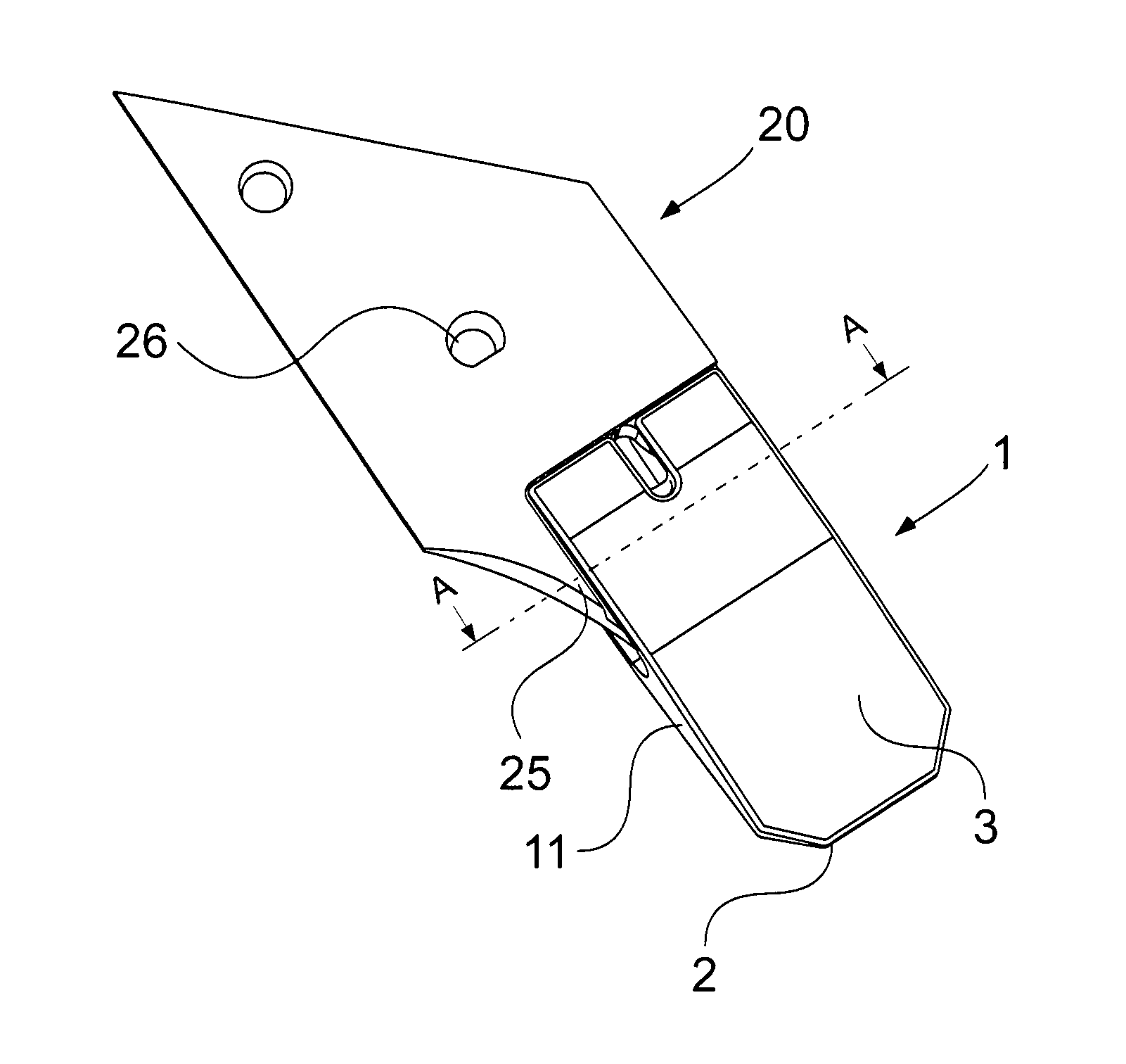
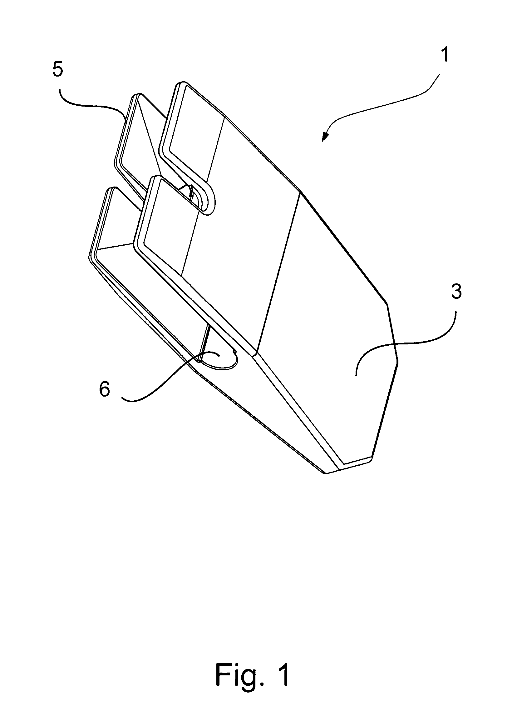
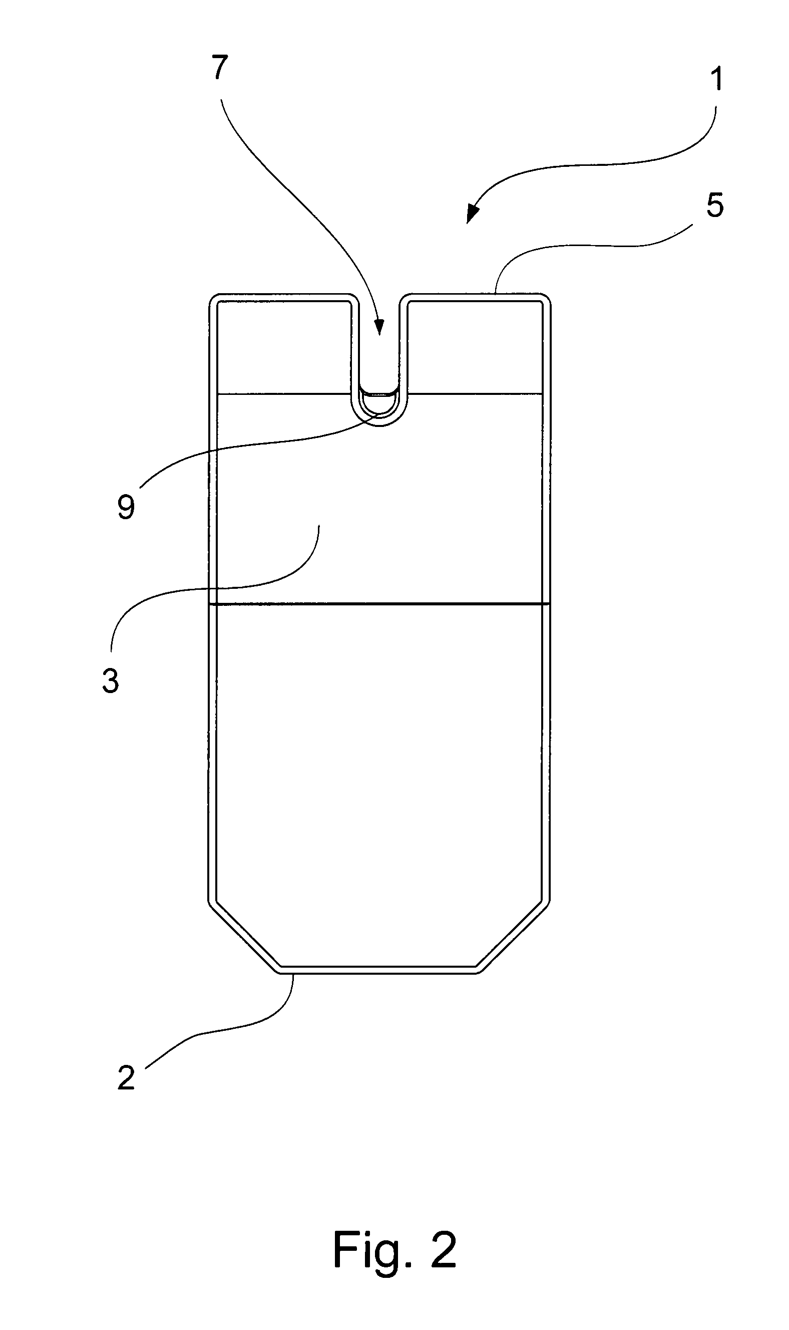
[0055]An end bit 1 for a soil-working tool comprises an edge 2 or the like, which edge 2 is intended for engaging with the soil, and a first wear face 3 and a second wear face 4.

[0056]At its trailing edge 5, the end bit 1 is provided with one or more openings 6 for receiving coupler(s) 21, 41 from a holder part 20, 40.

[0057]Likewise, the end bit 1 can be provided with a longitudinally extending hole or a slot 7, wherein a tool (not shown) can be inserted to the effect that the end bit 1 can be released from its engagement with the coupler(s) 21, 41 of the holder part 20, 40.

[0058]In connection with the bottom of the slot 7, a kind of step 9 or the like may be provided which may serve as wear indicator. The wear indicator operates by it being possible to see when the material on the first wear face 3 of the end bit is flush with the step 9, which is when the time has come to reverse the end bit or replace it. The sam...


PUM


Abstract

The invention relates to a replaceable end bit for a soil-working tool, which end bit is retained by friction and wherein, at its trailing edge, the end bit is provided with one or more openings that is / are oriented rearwardly relative to the end bit and for receiving couplers from a holder part. The openings may have rounded faces, and the faces may face towards each other. The distance between the rounded faces is increased with the distance from the trailing edge of the end bit. The invention also relates to a holder part for a replaceable end bit for a soil-working tool, which end bit is retained by friction, and wherein the holder part is provided with pairs of protruding couplers, which protruding couplers are provided with a space, where the distance between the two protruding couplers is reduced with the distance from their end faces.

Description

FIELD OF THE INVENTION[0001]The invention relates to a replaceable end bit for a soil-working tool, which end bit is retained by friction, where the end bit is, at its trailing edge, provided with one or more openings that is / are oriented rearwardly relative to the end bit and for receiving coupler(s) from a holder part which openings has / have rounded faces.[0002]The invention also relates to a holder for a replaceable end bit for a soil-working tool, which end bit is retained by friction, where the holder part is provided with a pair of protruding couplers, which protruding couplers are provided with a space, where the distance between the two protruding couplers is reduced with the distance from their end faces and where the protruding couplers are provided with rounded faces that face towards each other.BACKGROUND OF THE INVENTION[0003]For soil-working tools, such as ploughs, harrows, subsoilers (soil decompactors), seed drills, dippers or grabs for excavators, one used to either...

Claims


Application Information

Patent Timeline
Patent Type & Authority Patents(United States)
IPC IPC(8): E02F9/28A01B15/06A01B23/02
CPCE02F9/2808A01B15/06A01B23/02
Inventor MOLLER, PER, H.
Owner MOLLSOR
Why Eureka
Try Eureka