Optochemical sensor

a technology of optochemical sensors and sensors, applied in the field of optochemical sensors, can solve problems such as measuring accuracy, and achieve the effects of reducing the structural height of the overall device, enhancing the measuring accuracy of the system, and reducing the structural height of the optochemical sensor

Active Publication Date: 2017-10-17
TECSENSE
View PDF6 Cites 0 Cited by
  • Summary
  • Abstract
  • Description
  • Claims
  • Application Information

AI Technical Summary

Benefits of technology

[0014]According to a further development of the invention, the optochemical sensor is configured such that the excitation light source is embedded in the material thickness of the hood. With such a configuration, any unintentional stray light from the excitation light source in the direction of the detector or into the interior of the optochemical sensor will be safely prevented, and that part of the hood in which the excitation light source is integrated can, for instance, be formed with a larger material thickness than the remaining hood, which comprises reflectors so as to reflect, for instance, possibly present stray and, moreover, provide an effective separation of the excitation light source from the detector.
[0015]In that, as in correspondence with a further development of the invention, the sensor is configured such that a portion of the hood located between the excitation light source and the measuring element comprises a smoothened surface and is designed as an optical waveguide, it has become possible to use a portion of the hood directly as an optical waveguide such that the optochemical sensor can not only be simplified in terms of hardware but also further miniaturized. In addition, the generation of any stray light whatsoever will be effectively avoided by such a configuration.

Problems solved by technology

The integration of such optochemical sensors in chips involves the recurring problem that the sensors require a separation of the fluorescence light from the excitation light by means of a spectrometer or by using optical filters, which has turned out to be unsatisfactory, since the intensity of the excitation light is usually significantly higher than the intensity of the generated fluorescence light, which constitutes a problem for the measuring accuracy, in particular in miniaturized systems, since stray light might disturb or falsify measurements.

Method used


Image

  • Optochemical sensor
  • Optochemical sensor

Examples


Embodiment Construction

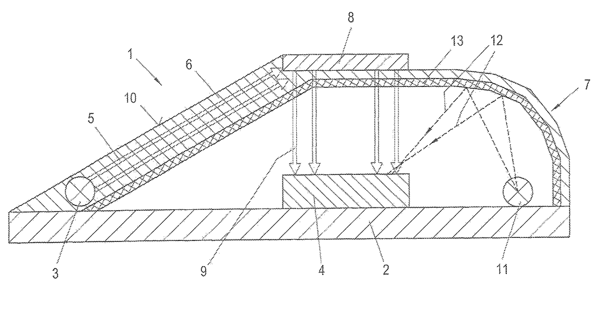
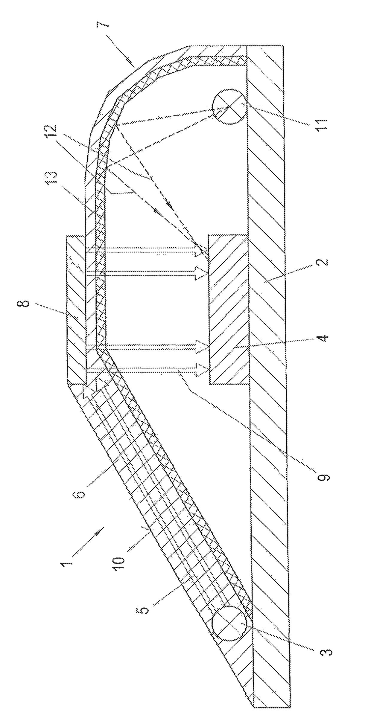
[0027]In FIG. 1, an optochemical sensor is denoted by 1, in which an excitation light source 3 and a detector 4 are fixed to a base plate 2. Light from the excitation light source 3, which is schematically indicated by 5, is radiated to a measuring element 8 through a portion 6 of a hood 7, which portion is designed as a light guide. The measuring element 8, which, in this case, is comprised of fluorophore dissolved or dispersed in a polymer base material, is, in particular, cross-linked with a surface roughened in the region of the measuring element 8, of the hood 7.

[0028]The excitation light source 5 excites the molecules of the fluorophore contained in the measuring element to emit fluorescence light, which fluorescence light contacts the molecules of a sample to be assayed and is optionally extinguished by said molecules. Non-extinguished light is reflected on the detector 4, and from measuring the intensity of the reflected radiation 9, which may optionally even be increased, t...


PUM

PropertyMeasurementUnit
thicknessaaaaaaaaaa
fluorescenceaaaaaaaaaa
pHaaaaaaaaaa

Abstract

An optochemical sensor comprises a measuring element excitable by the light of an excitation light source and in contact with a medium to be measured, and a measuring arrangement including at least one excitation light source and a detector as well as a hood separating the measuring arrangement from the measuring element, wherein the excitation light source and the detector are fixed to a base plate arranged in parallel with the measuring element, the hood, the excitation light source and the detector are separated from one another by at least a portion of the material thickness of the hood, and light from the excitation light source through an optical waveguide impinges on the measuring element at such an angle that fluorescence light emitted by the measuring element impinges perpendicularly on the detector.

Description

[0001]The present invention relates to an optochemical sensor comprising a measuring element excitable by the light of an excitation light source and in contact with a medium to be measured, and a measuring arrangement including at least one excitation light source and a detector as well as a hood separating the measuring arrangement from the measuring element.BACKGROUND OF THE INVENTION[0002]Optochemical sensors have been used to an increasing extent for measuring a great variety of fluids such as gases, liquids or even, mixtures thereof, both in the medical, biological or biochemical field and in the food and other laboratory or industrial sectors in order to enable the rapid and reliable detection of the presence or absence of specific substances. Gases whose presence or absence is determined by such sensors, for instance, include oxygen, CO2, but also, for instance, ozone or ammonia. Furthermore, such sensors have allowed, for instance in the medical field by measuring biomolecu...

Claims


Application Information

Patent Timeline
Patent Type & Authority Patents(United States)
IPC IPC(8): G01N21/77G01J3/02G01J3/44G01N21/64
CPCG01N21/77G01J3/0202G01J3/0272G01J3/0291G01J3/4406G01N21/643G01N21/645G01N21/6428G01N21/7703G01N2021/6419G01N2021/6432G01N2021/6441G01N2021/6484G01N2021/7786G01N2021/7793G01N2021/7796G01N2201/064G01N2201/022G01N2201/0228
Inventor RIBITSCH, VOLKERKROTTMAIER, JOHANNES
Owner TECSENSE
Why Eureka
Try Eureka