Can of a Drive Motor for a Pump Assembly

a drive motor and pump assembly technology, applied in mechanical equipment, machines/engines, electric/magnetic/electromagnetic heating, etc., can solve the problems of reducing the efficiency ensuring the desired pressure strength, and reducing the size of the drive motor, so as to reduce the size and width. , the effect of increasing the thickness of the material

Active Publication Date: 2010-12-09
GRUNDFOS MANAGEMENT AS
View PDF13 Cites 2 Cited by
  • Summary
  • Abstract
  • Description
  • Claims
  • Application Information

AI Technical Summary

Benefits of technology

[0036]According to further special embodiment of the method, the injection molding tool, in which the can is formed, comprises a gap which is designed for forming a radially extending collar at the open end of the can to be manufactured. During the solidification of the plastic, which is injected into the injection molding tool and thus is also injected into this gap, a pressure is exerted on at least one of the walls of the injection molding tool which defines this gap, wherein this pressure is directed towards the opposite wall of the gap. I.e. the gap is narrowed in its width by moving the walls apart. For this, the tool preferably has a base plate which lies opposite the outer mold part. This base plate is distanced to the outer mold part, in order to define the gap for forming the collar. The base plate during the solidification is moved onto the outer mold part, so that the gap is reduced in size. This method is particularly advantageous, if the gap has a larger width than the gap between the outer and inner mold part which defines the peripheral wall of the can to be manufactured. It is possible in this manner to manufacture a can with a very thin peripheral wall, which despite this has a collar of a larger material thickness at its open face-end. By applying a pressure force onto the wall of the gap forming the collar or by reducing the gap width during the solidification, one prevents bubbles (blowholes) or similar cavities from being able to form in this region on account of the shrinkage of the plastic on solidification.

Problems solved by technology

This however has the disadvantage that they compromise the magnetic field between the stator and the rotor.
With the cans of plastic however, there exists the problem of ensuring the desired pressure strength, given larger pump pressures.
However, the distance between the rotor and the stator increases with an increasing thickness of the can in the radial direction, whereby the efficiency of the drive motor is worsened.

Method used


Image

  • Can of a Drive Motor for a Pump Assembly
  • Can of a Drive Motor for a Pump Assembly
  • Can of a Drive Motor for a Pump Assembly

Examples


Embodiment Construction

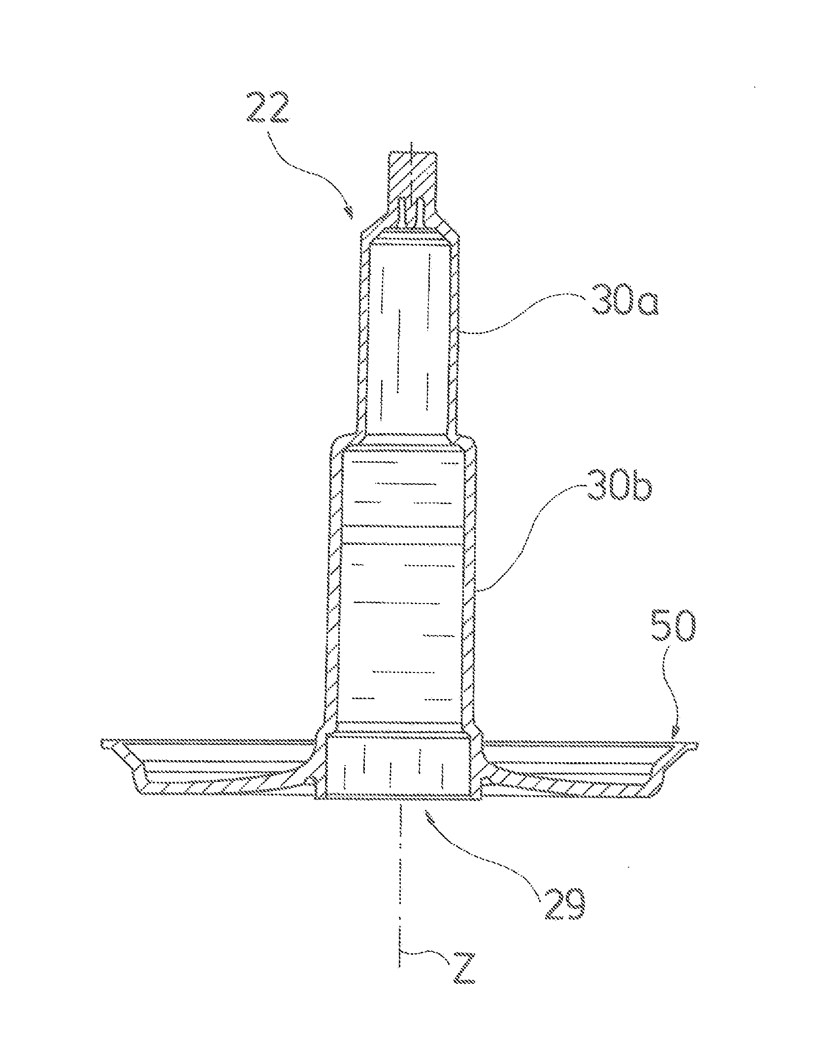
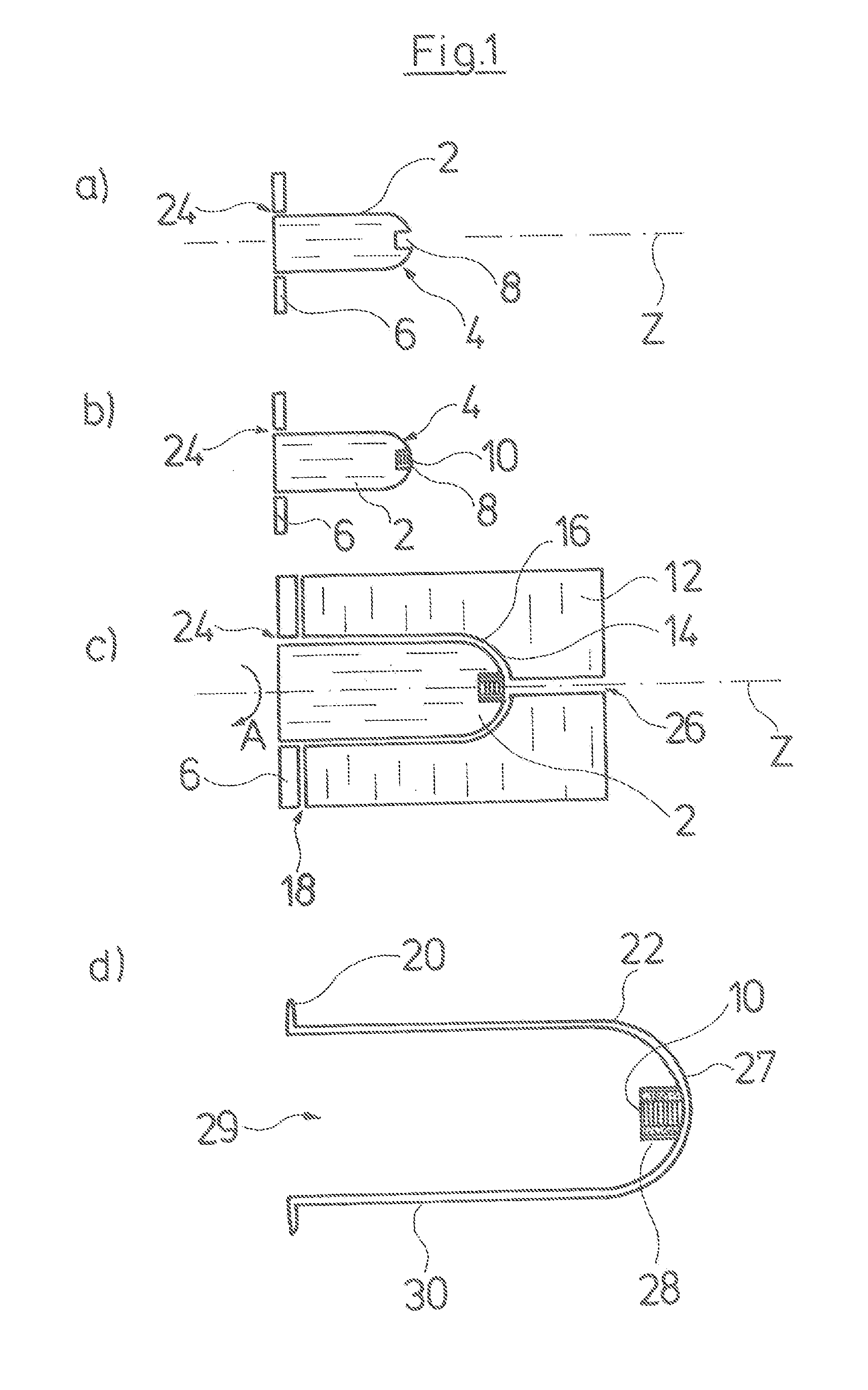
[0050]First, in a stepwise manner, the manufacture of a can according to the invention is explained by the FIGS. 1a to 1d. FIG. 1a schematically shows an inner mold part 2 or a core 2 of an injection molding tool for the manufacture of a can. The inner mold part 2 defines the shape of the inner space of the can to be manufactured. Thereby, a first axial end-side 4 defines the inner side of a base of a can to be manufactured. Such a can is designed closed by a base at one axial end, i.e. in a pot-like manner. The opposite axial end of the can is designed in an open manner and is the axial end which is later applied onto a pump housing. The inner mold part 2 at its end distant to the end-side 4 is attached on a base plate 6, for forming this open axial end of the can. The base plate 6 extends radially outwards normally to the longitudinal axis Z of the can to be manufactured or the inner mold part 2. A central recess 8 is formed on the axial end-side 4, and serves for receiving a bear...


PUM

PropertyMeasurementUnit
hardnessaaaaaaaaaa
stiffnessaaaaaaaaaa
axial lengthaaaaaaaaaa

Abstract

A can of a drive motor is provided for a pump assembly, wherein the can (22) is manufactured at least partly of plastic (52). At least in a part of the can (22) the plastic (52) is reinforced by individual fibers (32) distributed in the plastic (52). The fibers (32) in at least one layer (35) of the can (32) are aligned in a defined manner in the peripheral direction with respect to the longitudinal axis (Z) of the can (22). A method for manufacturing such a can is also provided.

Description

CROSS-REFERENCE TO RELATED APPLICATIONS[0001]This application is a Section 371 of International Application No. PCT / EP2008 / 007507, filed Sep. 12, 2008, which was published in the German language on Apr. 2, 2009, under International Publication No. WO 2009 / 039967 A1 and the disclosure of which is incorporated herein by reference.BACKGROUND OF THE INVENTION[0002]The invention relates to a can of a drive motor for a pump assembly, as well as to a method for the manufacture of such a can. Such a pump assembly may for example be a heating circulation pump assembly.[0003]The drive motors of such pump assemblies are designed as wet-runners, wherein a can is arranged between the stator space and the rotor space, and this separates the fluid filled rotor space from the dry stator space. Until now, such cans have mostly been manufactured of metal. This however has the disadvantage that they compromise the magnetic field between the stator and the rotor. For this reason, it is preferable to ap...

Claims


Application Information

Patent Timeline
Patent Type & Authority Applications(United States)
IPC IPC(8): H02K5/02B29C45/14
CPCB29C45/0005B29C45/1418B29C45/14631B29C45/14786B29C45/5605B29C70/48H02K15/14H02K5/02F04D13/0626F04D13/0633H02K5/128Y10T29/49009
Inventor HANSEN, JORN TOFTEGAARDLARSEN, TOM EKLUNDHHOJ, FINN MATHIESEN
Owner GRUNDFOS MANAGEMENT AS
Why Eureka
Try Eureka