

Beverage dispenser
a beverage dispenser and dispenser technology, applied in the field of beverage dispensers, can solve the problems of difficult lifting of the container in a stable manner, difficult to use up drinking water in the container, and inability to drop the remaining drinking water into the tank, etc., and achieve the effect of eliminating the negative pressure in the container
Inactive Publication Date: 2014-11-04
COSMO LIFE
View PDF18 Cites 10 Cited by
- Summary
- Abstract
- Description
- Claims
- Application Information
AI Technical Summary
Benefits of technology
The present invention is a beverage dispenser that uses air to eliminate negative pressure in the container and allows water to flow automatically. The dispenser has a water passage tube with a cross-section that is partitioned into a water passage and an air passage. An air passage pipe is connected to the air passage and hangs into the tank. A second on-off valve is provided at the free end of the air passage pipe and is opened when the water level in the tank lowers. This allows air in the tank to flow into the container, eliminating negative pressure and allowing water to be dropped into the tank. The air introduced into the container is cleaner than outer air, reducing the likelihood of contamination. The invention allows for automatic and spontaneous use of the drinking water in the container.
Problems solved by technology
This generates a negative pressure in the container, making it impossible to drop the remaining drinking water in the container into the tank.
Thus, it is impossible to use up drinking water in the container, at least not automatically.
In order to transfer such water remaining in the container into the tank, it is necessary to lift the raw water container until its outlet port separates from the container connecting portion, and incline the container to admit air into the container, thereby eliminating the negative pressure in the container. has to be the drinking water But since the raw water container is located at a high level, it is difficult to lift the container in a stable manner.
Also, drinking water may spill around the container connecting portion.
Method used
View moreImage
Smart ImageViewing Examples

Examples
first embodiment
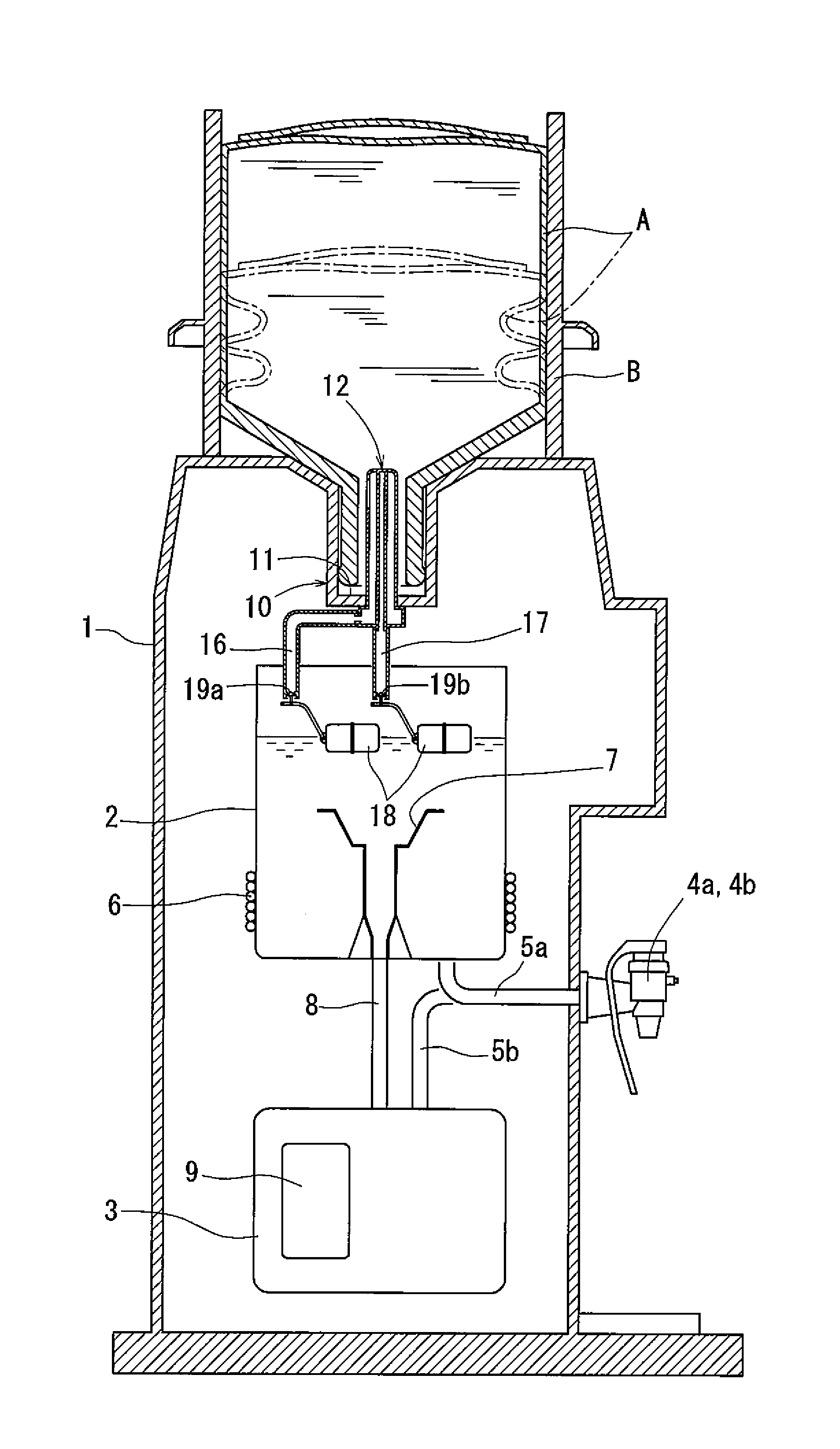
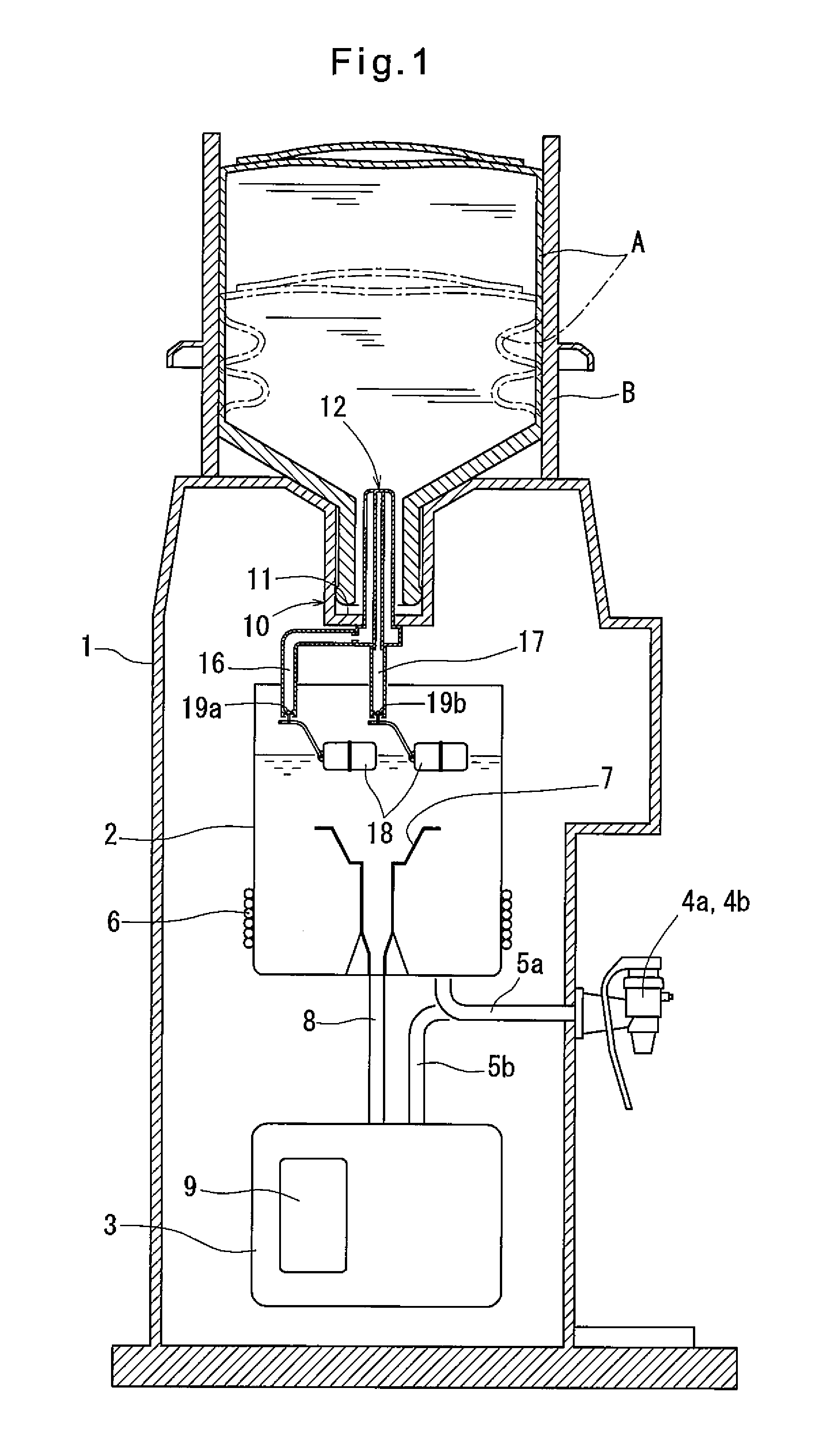
[0016]FIG. 1 is a vertical sectional view of a beverage dispenser according to a
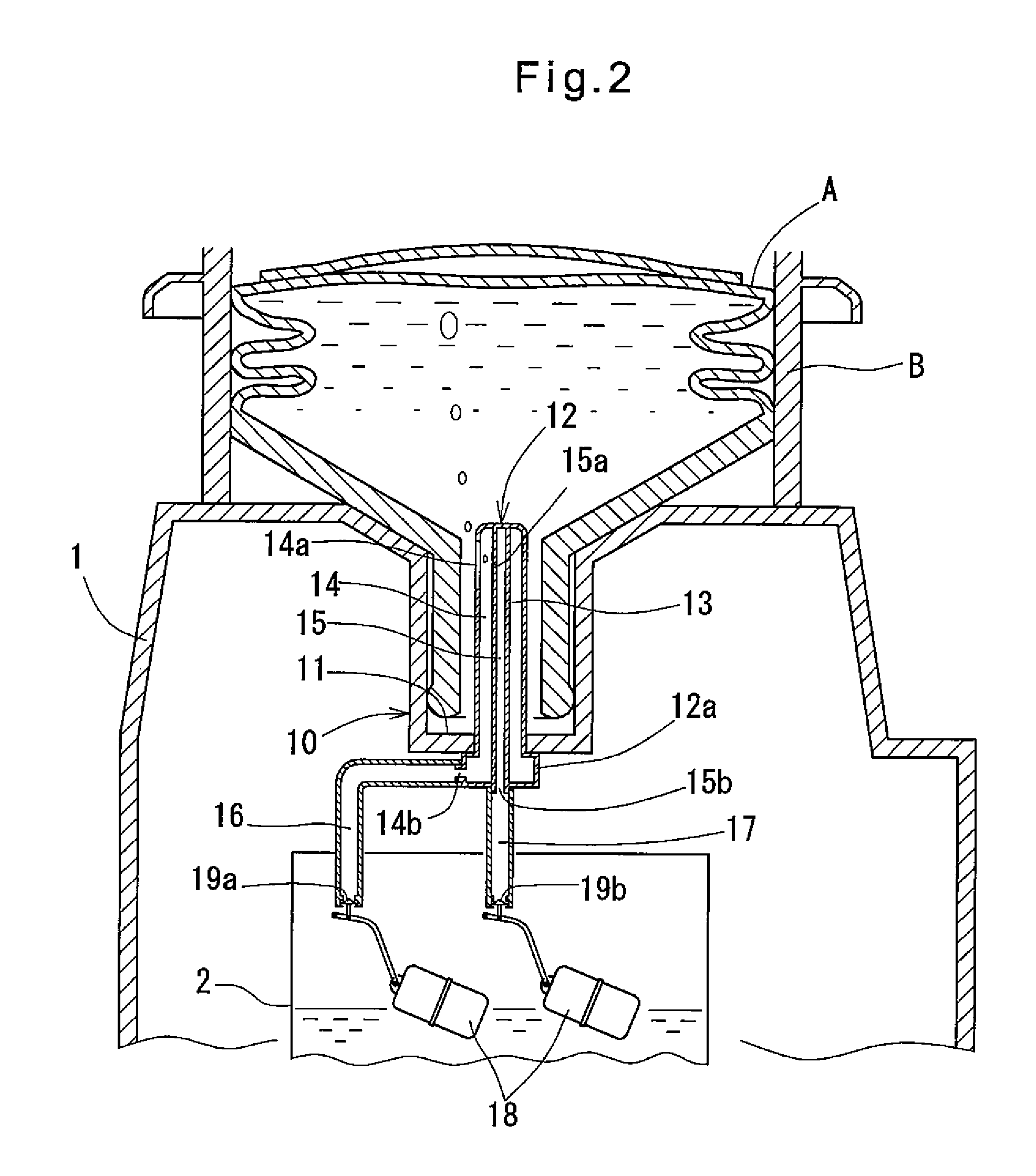
[0017]FIG. 2 is an enlarged vertical sectional view of an upper portion of FIG. 1.
[0018]FIG. 3(a) is a vertical sectional view of a container connecting portion of FIG. 2; and FIG. 3(b) is a sectional view taken along line of FIG. 3(a).
second embodiment
[0019]FIG. 4 is an enlarged vertical sectional view of an upper portion of a beverage dispenser according to a
[0020]FIG. 5(a) is a vertical sectional view of a container connecting portion of FIG. 4; and FIG. 5(b) is a sectional view taken along line V-V of FIG. 5(a).
[0021]FIG. 6 is a vertical sectional view of a modification of FIG. 4.
Login to View More PUM
| Property | Measurement | Unit |
|---|---|---|
| diameter | aaaaa | aaaaa |
| diameter | aaaaa | aaaaa |
| diameter | aaaaa | aaaaa |
Abstract
A beverage dispenser is proposed which includes a soft raw water container and which makes it possible to spontaneously use up drinking water in the container. A water passage tube (12) of a container connecting portion (10) includes a tubular partitioning wall (13) dividing the interior of the water passage tube (12) into a water passage (14) communicating with a water passage hole (14a), and an air passage (15) communicating with the water passage (14) through a small air passage hole (15a). A water passage pipe (16) is connected to the water passage (14). The water passage tube (12) has a base portion (12a) formed with an opening (15b) communicating with the air passage (15). An air passage pipe (17) is connected to the opening (15b) and hangs vertically downwardly into a low-temperature tank (2). An on-off valve (19b) is provided at the free end of the air passage pipe (17) which is adapted to open when the water level in the low-temperature tank (2) lowers. With this arrangement, when drinking water in the raw water container (A) runs low and the water level in the low-temperature tank (2) remains low, air in the low-temperature tank (2) is introduced into the raw water container (A) through the on-off valve (19b), which is now open, the air passage pipe (17), the air passage (15) and the small air passage hole (15a). This eliminates a negative pressure in the raw water container (A), thereby allowing water remaining in the container to be dropped into the tank.
Description
TECHNICAL FIELD[0001]The present invention relates to a beverage dispenser for dispensing drinking water transferred from a raw water container into a tank through an outlet valve.BACKGROUND ART[0002]There is known a beverage dispenser comprising a raw water container for holding drinking water therein, a container connecting portion to which the outlet port of the raw water container can be connected with the outlet port facing downward, a tank provided under the connecting portion for holding drinking water dropped from the raw water container, and an outlet valve through which drinking water in the tank can be dispensed. In some of such beverage dispensers, a raw water container is used which is made of a soft material so that its side wall has flexibility (see e.g. Patent document 1).[0003]Such a raw water container can be collapsed during transportation, so that it can be transported efficiently. During use, as drinking water in the container drops, the container is gradually c...
Claims
Login to View More Application Information
Patent Timeline
 Patent Type & AuthorityPatents(United States)
IPC IPC(8): B67D7/14B67D3/00B67D1/00
CPCB67D3/0032B67D3/0009B67D3/0022B67D3/0038Y10T137/3127B67D3/00F16K31/18
InventorSHIOTANI, NANASHIOTANI, MASARU
OwnerCOSMO LIFE