
Automatic VGA monitor detection

a monitor detection and automatic technology, applied in static indicating devices, instruments, cathode-ray tube indicators, etc., can solve the problems of failure to detect the connection, computer may not detect, and software-dependent monitor control is plagued by reliability problems, so as to achieve reliable detection and fast rate

Active Publication Date: 2014-11-04
MAXIM INTEGRATED PROD INC
View PDF3 Cites 9 Cited by
  • Summary
  • Abstract
  • Description
  • Claims
  • Application Information

AI Technical Summary

Benefits of technology

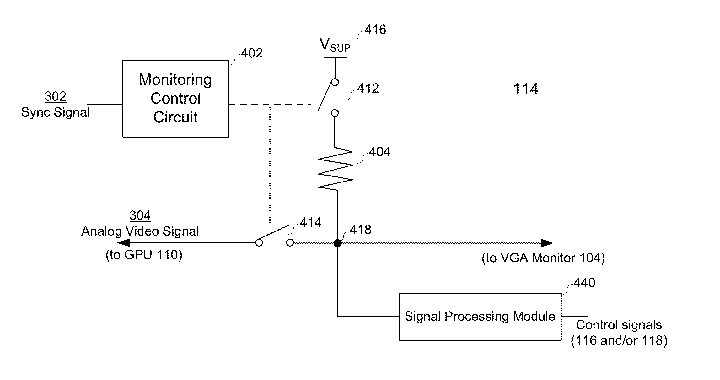
The present invention relates to detecting the presence of a VGA display on a computer using a monitor detection module. The module uses horizontal or vertical synchronization pulses to monitor the termination resistance of a video signal line, allowing for reliable detection of the VGA display at a fast rate without interfering with video signal transmission.

Problems solved by technology

Despite of acceptable performance in most cases, software-dependent monitor control is plagued with reliability issues.
In many occasions, the computer may not detect the VGA monitor right upon connection, and sometimes, may even fail to detect the connection.
Moreover, the software operating system often fails to detect that a VGA monitor is powered off although it is still connected to the graphics hardware of the computer.
Software-dependent monitor control is also plagued with energy and cost efficiency problems that are associated with some of the aforementioned reliability issues.
As a result, the graphics hardware consumes redundant power, which is not desirable as energy requirements get stringent for future products.
Cost efficiency is largely degraded due to material and assembly cost.

Method used


Image

  • Automatic VGA monitor detection
  • Automatic VGA monitor detection
  • Automatic VGA monitor detection

Examples


Embodiment Construction

[0024]In the following description, for purposes of explanation, specific details are set forth in order to provide an understanding of the invention. It will be apparent, however, to one skilled in the art that the invention can be practiced without these details. One skilled in the art will recognize that embodiments of the present invention, described below, may be performed in a variety of ways and using a variety of structures. Those skilled in the art will also recognize additional modifications, applications, and embodiments are within the scope thereof, as are additional fields in which the invention may provide utility. Accordingly, the embodiments described below are illustrative of specific embodiments of the invention and are meant to avoid obscuring the invention.

[0025]Reference in the specification to “one embodiment” or “an embodiment” means that a particular feature, structure, characteristic, or function described in connection with the embodiment is included in at ...


PUM


Abstract

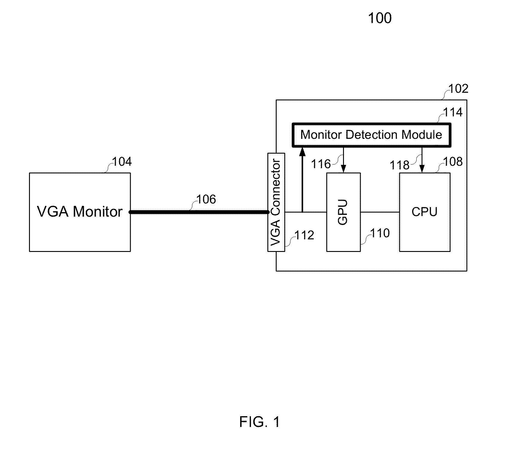
Various embodiments of the present invention relate to methods, systems and devices of employing a monitor detection module in a computer to automatically detect the presence of a VGA display. Such a system for automatic VGA monitor detection comprises a central processing unit (CPU), a GPU, a VGA connector and the monitor detection module. The CPU provides image information to the GPU which further processed the image information to generate video signals according to a VGA display standard. The video signal comprises analog video signals (i.e., red, green and blue) and synchronization signals (i.e., horizontal and vertical). The video signals are transmitted to the VGA connector at the interface of the computer. A VGA monitor or projector may be connected to the computer at the VGA connector via a VGA data cable. The monitor detection module receives at least one of the analog video signals and at least one of the sync signals, identifies a monitor detection pulse synchronous with the sync signal, and monitors the impedance at the pin for the analog video signal at the VGA connector during the monitor detection pulse. The monitor detection module takes advantage of synchronization pulses in the horizontal or vertical sync signal to monitor termination resistance of an analog video signal line, and thus, the VGA display may be detected reliably at a fast rate without interfering with video signal transmission.

Description

BACKGROUND[0001]A. Technical Field[0002]The present invention relates generally to integrated circuits, and more particularly to methods, systems and devices of employing a monitor detection module in a computer or computer system to detect the presence of a VGA display. The monitor detection module takes advantage of synchronization pulses in a horizontal or vertical sync signal to monitor termination resistance of an analog video signal line, and thus, the VGA monitor may be detected reliably at a fast rate while not interfering with video signal transmission.[0003]B. Background of the Invention[0004]Video Graphic Array (VGA) refers to the display hardware first introduced by IBM in 1987, and thereafter, has been widely adopted as an analog display standard by personal computers, e.g., desktop, laptop and tablet computers. A VGA monitor or projector may be employed not only as a primary display device but also as a secondary display device in these personal computers.[0005]In toda...

Claims


Application Information

Patent Timeline
Patent Type & Authority Patents(United States)
IPC IPC(8): G06F13/14
CPCG06F13/14G09G5/00G09G5/006G09G2370/042G09G2370/22
Inventor VAN, SCHERRENBURG, MICHEAL, ANTHONIUS
Owner MAXIM INTEGRATED PROD INC
Learn More