Abscissa calibration jig and abscissa calibration method of laser interference measuring apparatus

a laser interference and calibration method technology, applied in the direction of measuring devices, instruments, using optical means, etc., can solve the problems of inability to accurately perform correction or the like, image distortion, and limited contour shape, etc., to achieve easy and precise calibration

Active Publication Date: 2014-11-04
MITUTOYO CORP
View PDF20 Cites 3 Cited by
  • Summary
  • Abstract
  • Description
  • Claims
  • Application Information

AI Technical Summary

Benefits of technology

[0012]A primary object of the invention is to provide an abscissa calibration jig and an abscissa calibration method of a laser interference measuring apparatus having a convergent optics, in which a position on a measuring plane in the laser interference measuring apparatus can be calibrated easily and precisely.
[0014]In such an abscissa calibration jig according to the invention, the image projection unit is supported by the first support mechanism and the second support mechanism and rotated around the first rotation axis and the second rotation axis so that an image can be projected in an arbitrary direction. In order to calibrate the laser interference measuring apparatus, the abscissa calibration jig is disposed so that the focal position of a convergent optics of the laser interference measuring apparatus to be calibrated aligns with the rotation center of the abscissa calibration jig. In this state, an image is projected from the image projection unit so that the image is received by the light receiving unit of the laser interference measuring apparatus. The projected image has a marker at one point on the image. Distortion or the like in the convergent optics of the laser interference measuring apparatus can be detected by examination of the correspondence between the coordinates (corresponding to actually measured abscissas of the marker or abscissas in the light receiving unit) of the marker and the coordinates (corresponding to reference abscissas of the marker or the abscissas in an object to be measured) calculated from the current angle positions of the first support mechanism and the second support mechanism of the abscissa calibration jig. Such correspondence between the abscissas is examined on a part or all of points on the light receiving unit, and correction values are calculated so that the abscissas of the laser interference measuring apparatus can be calibrated easily and precisely.
[0019]In such an abscissa calibration method according to the invention, distortion or the like in the convergent optics of the laser interference measuring apparatus can be detected by examination of correspondence between the coordinates (corresponding to actually measured abscissas of the marker or abscissas in the light receiving unit) of the marker and the coordinates (corresponding to reference abscissas of the marker or the abscissas in an object to be measured) calculated from the current angle positions of the first support mechanism and the second support mechanism of the abscissa calibration jig. Such correspondence between the abscissas is examined on a part or all of points on the light receiving unit, and correction values are calculated so that the abscissas of the laser interference measuring apparatus can be calibrated easily and precisely.

Problems solved by technology

That is, when there is an abnormal value in the measured data, correction or the like cannot be performed accurately if the point where the abnormal value has occurred cannot be identified precisely.
On the other hand, when the spherical surface shape of an object to be measured is measured using a convergent optics, image distortion is also produced when the spherical shape is developed into a planar image in a two-dimensional imaging device, in addition to the image distortion or the difference between longitudinal and lateral magnifications.
However, the contour shape is limited to a circle in the case of JP-A-2007-327892.
Such a method has an effect in evaluation of a lower-order abscissa error such as a difference between longitudinal and lateral in magnifications, but has a limited effect in evaluation of an abscissa error which has a higher-order term or which is nonlinear.
Even in the present level of technology, however, it is supposed that production of a diffraction grating as in JP-A-2002-206915 involves great difficulty.
It is not easy to manufacture such an element strictly.
Further, when such a planar object to be measured is placed in a convergent optics, it is difficult to adjust the focus of the interferometer all over the visual field of an image.
There may be considered a problem that it is difficult to perform precise measurement for evaluating the abscissa.

Method used


Image

  • Abscissa calibration jig and abscissa calibration method of laser interference measuring apparatus
  • Abscissa calibration jig and abscissa calibration method of laser interference measuring apparatus
  • Abscissa calibration jig and abscissa calibration method of laser interference measuring apparatus

Examples


first embodiment

[First Embodiment]

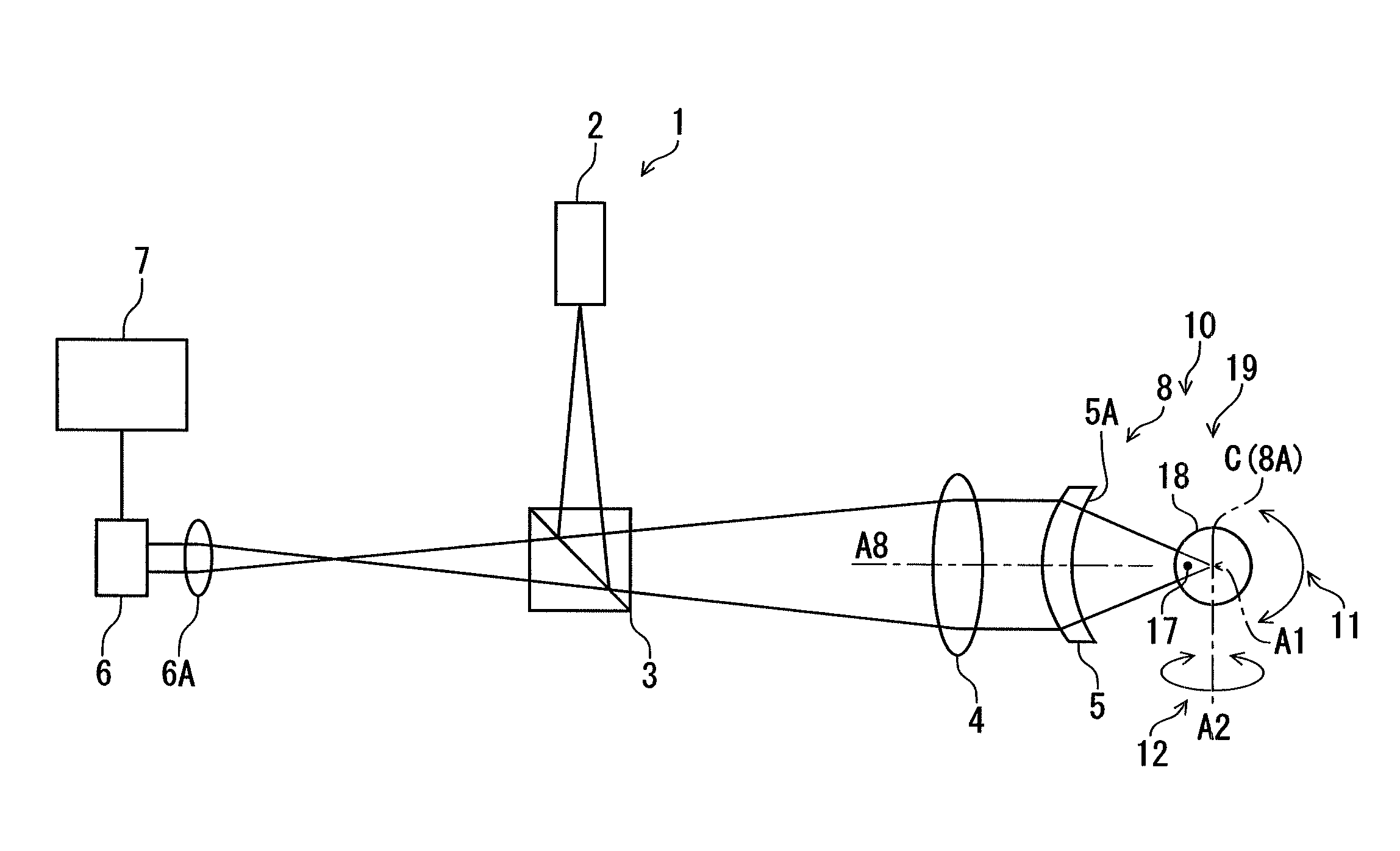
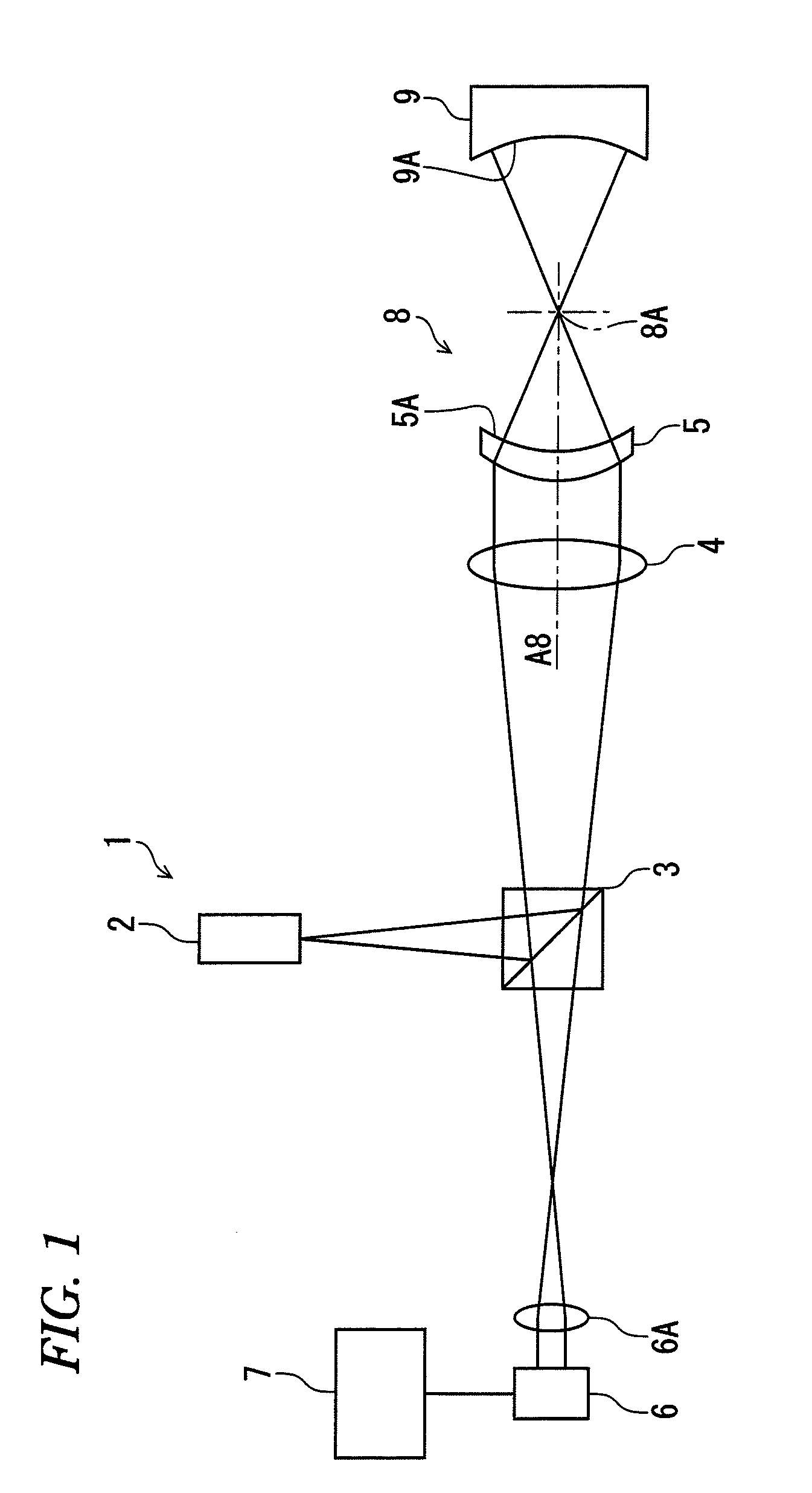
[0037]A first embodiment of the invention is shown in FIGS. 2 to 6. In this embodiment, an abscissa calibration jig 10 (see FIG. 2) according to the invention is applied to the aforementioned laser interference measuring apparatus 1 in FIG. 1 so as to calibrate the abscissas of the laser interference measuring apparatus 1 in a procedure based on an abscissa calibration method according to the invention.

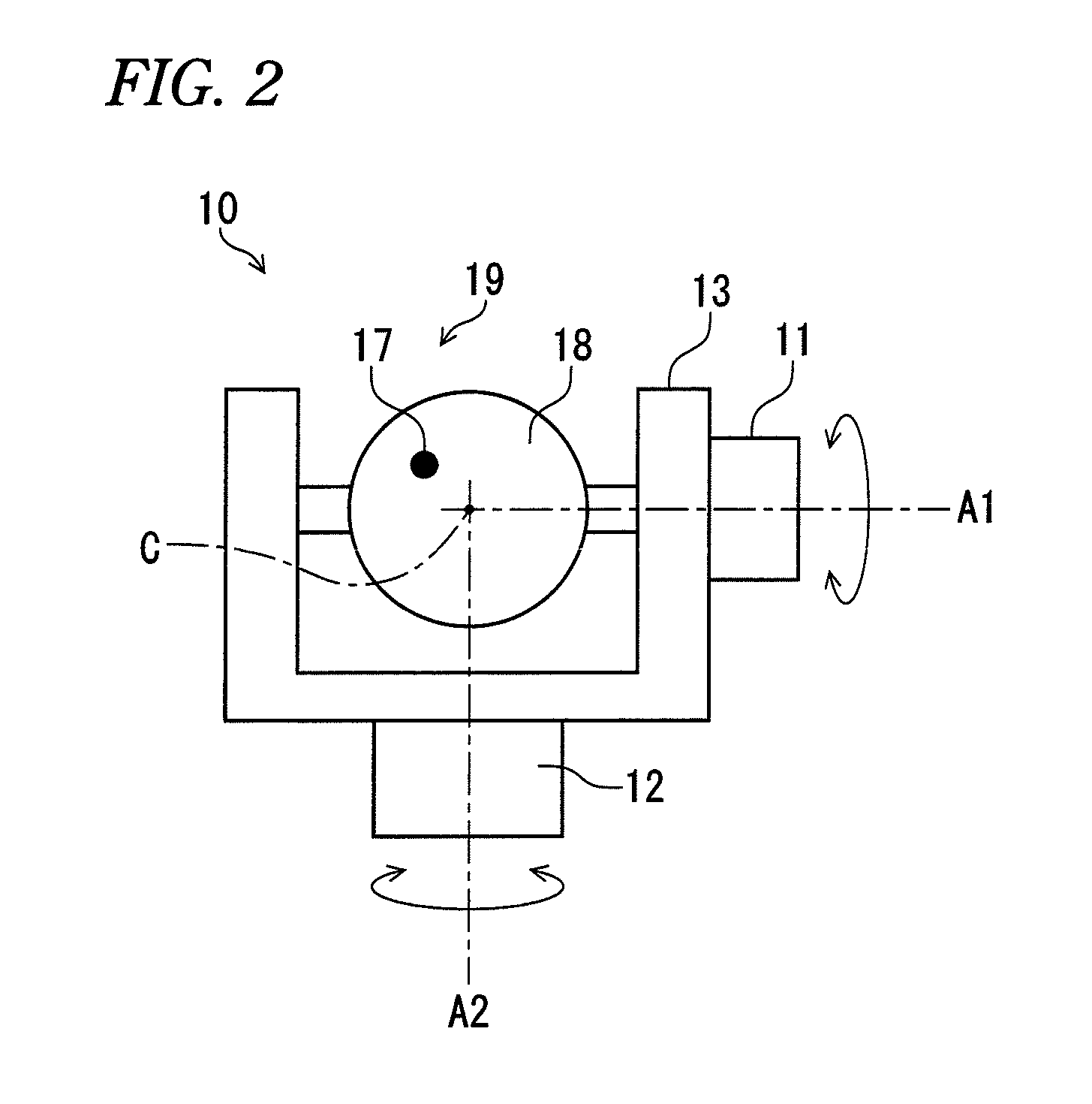
[0038]In FIG. 2, the abscissa calibration jig 10 has a first support mechanism 11, a second support mechanism 12, a frame 13 and an image projection unit 19. The first support mechanism 11 is placed on the frame 13 so as to support the image projection unit 19 rotatably around a first rotation axis A1. The first rotation axis A1 passes a predetermined rotation center C. The second support mechanism 12 supports the first support mechanism 11 through the frame 13 rotatably around a second rotation axis A2. The second rotation axis A2 crosses the first rotation axis A1 ...

second embodiment

[Second Embodiment]

[0055]FIGS. 7 to 11 show a second embodiment of the invention. In this embodiment, an abscissa calibration jig 20 (see FIG. 7) according to the invention is applied to the aforementioned laser interference measuring apparatus 1 in FIG. 1 so as to calibrate the abscissas of the laser interference measuring apparatus 1 in a procedure based on an abscissa calibration method according to the invention.

[0056]In FIG. 7, the abscissa calibration jig 20 has a first support mechanism 21, a second support mechanism 22, a frame 23 and an image projection unit 29. The first support mechanism 21 is placed on the frame 23 so as to support the image projection unit 29 rotatably around a first rotation axis A1. The first rotation axis A1 passes a predetermined rotation center C. The second support mechanism 22 supports the first support mechanism 21 through the frame 23 rotatably around a second rotation axis A2. The second rotation axis A2 crosses the first rotation axis A1 at t...


PUM


Abstract

An abscissa calibration jig of a laser interference measuring apparatus, includes: an image projection unit configured to project an image with a marker; a first support mechanism configured to rotatably support the image projection unit around a first rotation axis passing a predetermined rotation center; and a second support mechanism configured to rotatably support the first support mechanism around a second rotation axis crossing the first rotation axis at the rotation center.

Description

BACKGROUND[0001]1. Field of the Invention[0002]The present invention relates to an abscissa calibration jig and an abscissa calibration method of a laser interference measuring apparatus. Particularly, it relates to calibration of a position on a measurement plane in a laser interference measuring apparatus having a convergent optics.[0003]2. Description of the Related Art[0004]Apparatuses called laser interferometers or laser interference measuring apparatuses have been heretofore used widely for precisely measuring the surface texture or the surface shape of an object to be measured. A measured value obtained by the laser interference measuring apparatus is acquired as a measured value of the height of the surface of the object to be measured. The measured value is used as feedback data for evaluation of the shape of the surface of the object to be measured, the step of processing the object to be measured, or the like. In such an application, it is necessary to accurately know th...

Claims


Application Information

Patent Timeline
Patent Type & Authority Patents(United States)
IPC IPC(8): G01B11/00G01B9/02
CPCG01B11/00
Inventor HAGINO, TAKESHIYOKOYAMA, YUICHIROKURIYAMA, YUTAKA
Owner MITUTOYO CORP
Why Eureka
Try Eureka