Controlling a power amplifier based on transmitter output emissions

a power amplifier and output emission technology, applied in the field of radio frequency (rf) transmitters, can solve the problem of increasing the power dissipation of pa beyond the added margin

Active Publication Date: 2014-11-04
AVAGO TECH INT SALES PTE LTD
View PDF5 Cites 43 Cited by
  • Summary
  • Abstract
  • Description
  • Claims
  • Application Information

AI Technical Summary

Problems solved by technology

However, the added margin increases the power dissipation of the PA beyond what is needed to generate the desired output power under nominal conditions.

Method used


Image

  • Controlling a power amplifier based on transmitter output emissions
  • Controlling a power amplifier based on transmitter output emissions
  • Controlling a power amplifier based on transmitter output emissions

Examples


Embodiment Construction

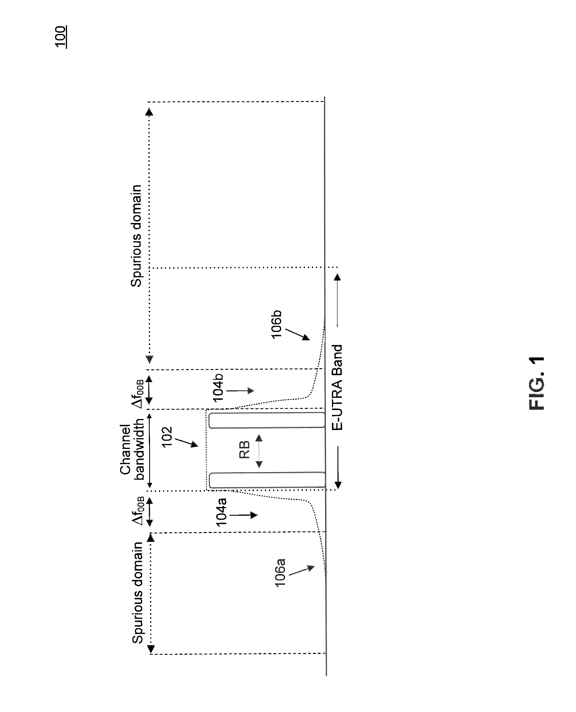
[0015]FIG. 1 illustrates an example User Equipment (UE) transmitter radio frequency (RF) spectrum 100 according to the Evolved-Universal Terrestrial Radio Access (E-UTRA) air interface standard. As shown in FIG. 1, example RF spectrum 100 consists of in-channel emissions 102, out-of-band (OOB) emissions 104a and 104b, and spurious emissions 106a and 106b.

[0016]In-channel emissions 102 include emissions that fall within the assigned E-UTRA channel bandwidth. The assigned E-UTRA channel bandwidth can be between 1.4 MHz and 20 MHz, depending on the number of resource blocks (RBs) being transmitted by the UE.

[0017]OOB emissions 104a and 104b include unwanted emissions that fall immediately outside the assigned channel bandwidth and within a ΔfOOB (MHz) interval from the upper and lower edges, respectively, of the assigned channel bandwidth. Typically, OOB emissions 104a and 104b results from the modulation process as well non-linear amplification in the UE transmitter. As further descr...


PUM


Abstract

Methods and systems for controlling the supply voltage provided to a power amplifier (PA) in a radio frequency (RF) transmitter based on measured output spectrum emissions are provided. In an embodiment, the PA supply voltage is adjusted such that spectrum emission limits are satisfied with predetermined margins. In another embodiment, the predetermined margins are reduced to lower power consumption of the PA.

Description

CROSS-REFERENCE TO RELATED APPLICATIONS[0001]The present invention claims the benefit of U.S. Provisional Application No. 61 / 494,842, filed Jun. 8, 2011, and U.S. Provisional Application No. 61 / 611,733, filed Mar. 16, 2012, both of which are incorporated herein by reference in their entireties.BACKGROUND[0002]1. Field of the Invention[0003]The present invention relates generally to radio frequency (RF) transmitters.[0004]2. Background Art[0005]Commonly, to ensure compliance with spectrum emission requirements, the supply voltage provided to the power amplifier (PA) in an RF transmitter is increased by a margin above the nominal supply voltage necessary to produce the desired output power of the PA. The margin accounts for variations in temperature, process (i.e., part-to-part variations), and load impedance. For example, commonly, the PA supply voltage is increased so as to achieve a 5 to 6 dB margin in the spectral mask measurements. However, the added margin increases the power di...

Claims


Application Information

Patent Timeline
Patent Type & Authority Patents(United States)
IPC IPC(8): H03F3/24H04L25/03H03G3/30H04K1/02H04L25/49H03F1/02
CPCH03G3/3042H03F3/24H03F1/0255H03F1/0233
Inventor XIA, YINGDAKSHINAMURTHY, SRIRAMANLORENZ, ROBERT
Owner AVAGO TECH INT SALES PTE LTD
Why Eureka
Try Eureka