Methods and apparatus for locking the optical phase of single-sideband amplitude-modulation signals

Active Publication Date: 2014-11-04
HRL LAB
View PDF2 Cites 16 Cited by
  • Summary
  • Abstract
  • Description
  • Claims
  • Application Information

AI Technical Summary

Benefits of technology

The present invention provides a method and system for carrier-suppressed amplitude modulation of a radio-frequency input signal using optical techniques. The method involves receiving a radio-frequency input signal and a radio-frequency locking signal, and using an electro-optic modulator to impress the signals onto an optical carrier. The carrier is then split to a signal arm and a local-oscillator arm, where the optical spectrum is generated. The optical spectrum is then filtered to remove unwanted sidebands and stabilize the differential phase between the signal arm and the local-oscillator arm. The system includes components such as receivers, a laser source, a coupler / splitter, and a photonic integrated circuit. The technical effects of the invention include improved stability and accuracy of the radio-frequency input signal, reduced interference and noise, and improved phase-stabilization for the radio-frequency output signal.

Problems solved by technology

Significant effort has been spent towards optical integrated circuits with high complexity and advanced functionality.
While amplitude modulation of RF signals is relatively insensitive to environmental changes, the same cannot be said for optical signals.
Hence even minor variations in the optical signal environment can produce unacceptable variations in the phase of the received optical signal.
To date, microresonators have not been utilized in conjunction with coherent-AM links.

Method used


Image

  • Methods and apparatus for locking the optical phase of single-sideband amplitude-modulation signals
  • Methods and apparatus for locking the optical phase of single-sideband amplitude-modulation signals
  • Methods and apparatus for locking the optical phase of single-sideband amplitude-modulation signals

Examples


Embodiment Construction

[0049]The methods and apparatus of the present invention will now be described in detail by reference to various non-limiting embodiments of the invention.

[0050]Unless otherwise indicated, all numbers expressing dimensions, frequencies, efficiencies, and so forth used in the specification and claims are to be understood as being modified in all instances by the term “about.” Without limiting the application of the doctrine of equivalents to the scope of the claims, each numerical parameter should at least be construed in light of the number of reported significant digits and by applying ordinary rounding techniques.

[0051]As used in this specification and the appended claims, the singular forms “a,”“an,” and “the” include plural referents unless the context clearly indicates otherwise.

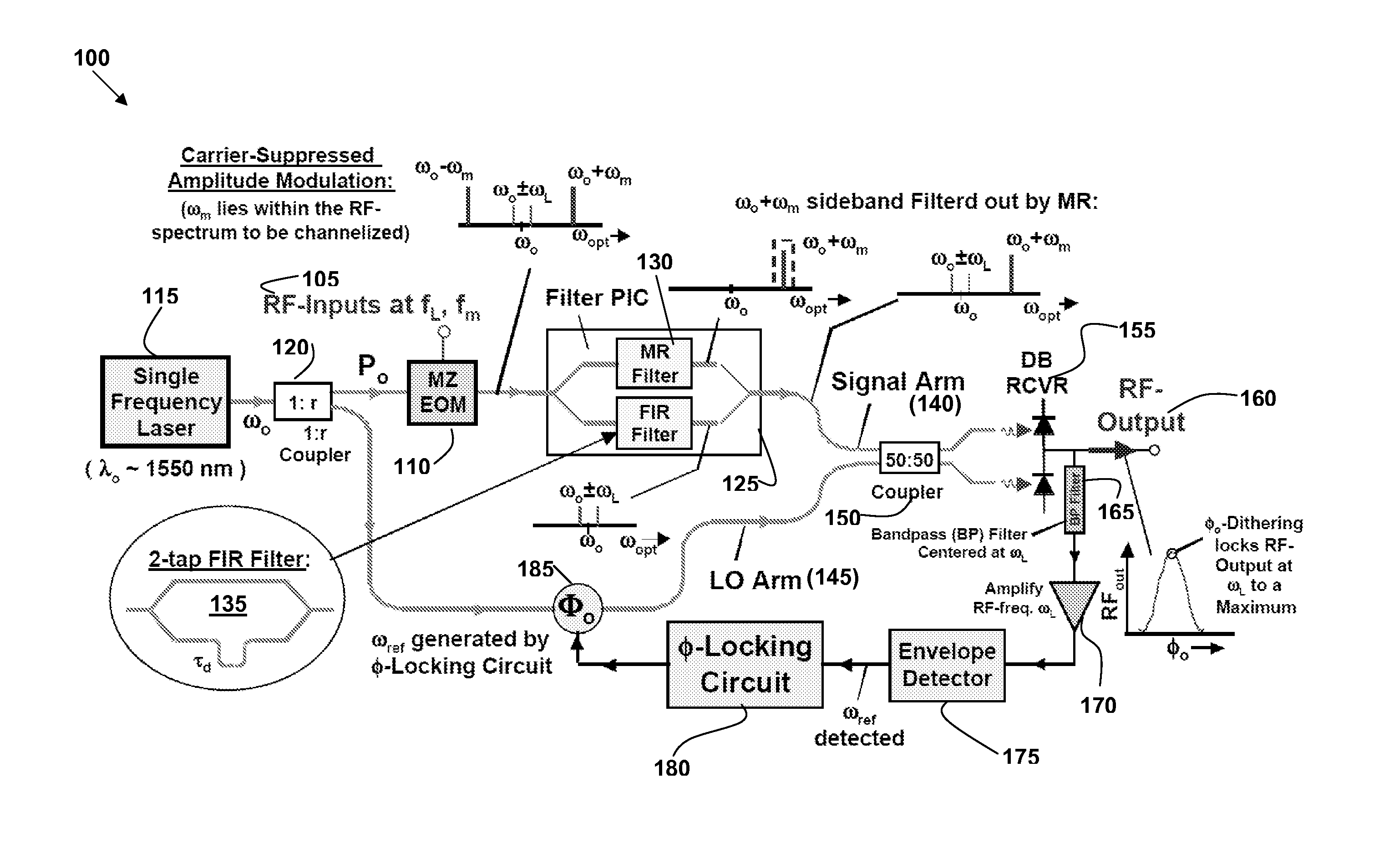
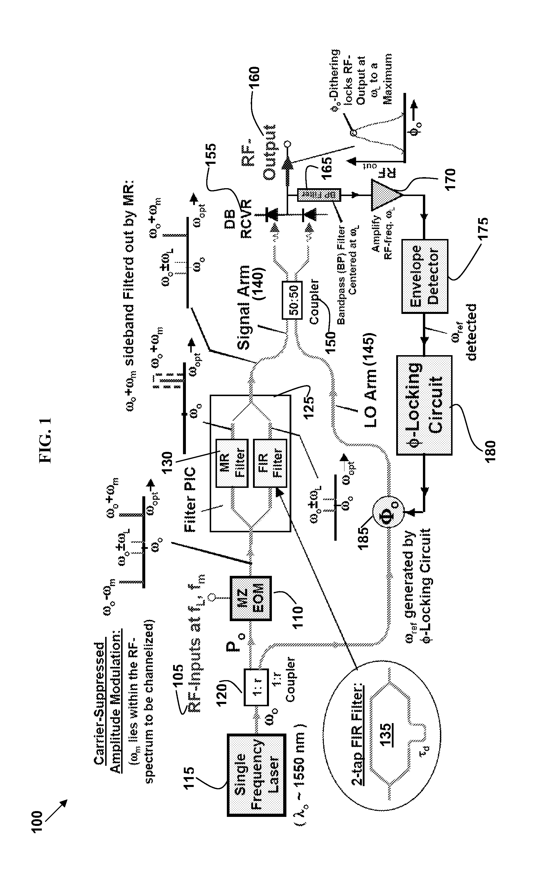
[0052]Some variations of this invention provide a method to lock the optical phase of a single-sideband (SSB), carrier-suppressed coherent amplitude-modulation (AM) analog optical link. By locking the o...


PUM


Abstract

This invention provides an approach to lock the optical phase of a single sideband, carrier-suppressed coherent-AM analog optical link, so that for example an RF signal can be transmitted with high fidelity over fibers. In some embodiments, a method comprises providing a RF locking signal; impressing an RF input signal and the RF locking signal onto the optical field of a suppressed carrier; introducing the optical spectrum to a photonic integrated circuit comprising a microresonator filter and a finite impulse response filter; selectively passing the double sideband, associated with the locking frequency, through the finite impulse response filter; and recovering a RF output signal, wherein a feedback loop provides dithering to stabilize the optical phase of the link and thus preserve amplitude / phase integrity for the RF-photonic signal. The disclosed method is especially suited to the filtering of RF-photonic signals via use of the resonance passbands derived from microdisks or micro-rings.

Description

FIELD OF THE INVENTION[0001]The present invention generally relates to communication systems, and more specifically to methods and devices for locking the optical phase of coherent-AM analog optical links.BACKGROUND OF THE INVENTION[0002]The ever-increasing demand for broadband communication systems has led to optical-transmission systems based on optical waveguides such as fiber optics and optical processing elements for use in these systems. Generally, in high-performance communication systems, photons continue to supplant electrons as data messengers. Significant effort has been spent towards optical integrated circuits with high complexity and advanced functionality.[0003]Amplitude modulation (AM) is well-known in electronic communications, most commonly for transmitting information via a radio carrier wave. Amplitude modulation works by varying the strength of the transmitted signal in relation to the information being sent. Amplitude modulation produces a modulated output sign...

Claims


Application Information

Patent Timeline
IPC IPC(8): H04B10/00H04J14/00
CPCH04B10/00H04B10/25759H04J14/00
Inventor NG, WILLIE W.PERSECHINI, DAVID L.
Owner HRL LAB
Why Eureka
Try Eureka