Method and system for single-sideband optical signal generation and transmission

Inactive Publication Date: 2003-12-09
AMERICAN TELEPHONE & TELEGRAPH CO
View PDF8 Cites 73 Cited by
  • Summary
  • Abstract
  • Description
  • Claims
  • Application Information

AI Technical Summary

Problems solved by technology

The interaction of chirp and chromatic dispersion in the fiber can cause system impairments.
Because of optical fiber dispersion, different frequency components will travel at different speeds, creating interference in the transmitted signals.
Although the two sidebands contain the same information, they travel at different speeds in the optical fiber and arrive at the receiver at different times. The net result is a power penalty and limit in the transmission distance.
Optical transmission systems employing baseband digital transmission, e.g., by on/off keying of the light, may also suffer from the effects of dispersion.
In long-distance transmission systems, dispersion can interact with non-linearities in the optical fiber, further impairing transmission.
Some optical fibers also suffer from polarization-mode-dispersion, which may vary with time due to strain and temperature variations.
It is difficult to compensate for this sort of dispersion.
In addition, some optical non-linearities, such as self-phase modulation, are worse in transmission systems with low dispersion.
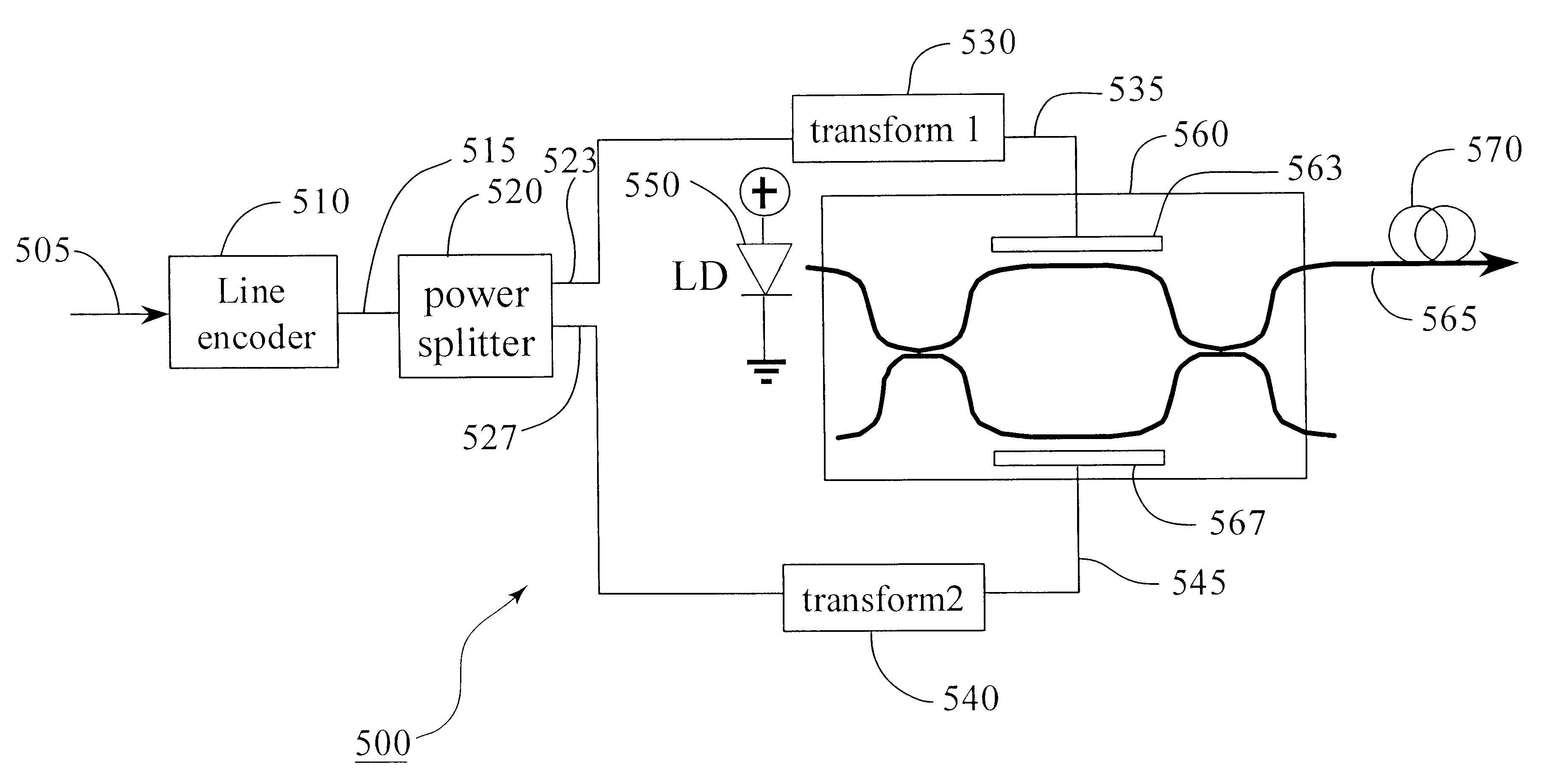
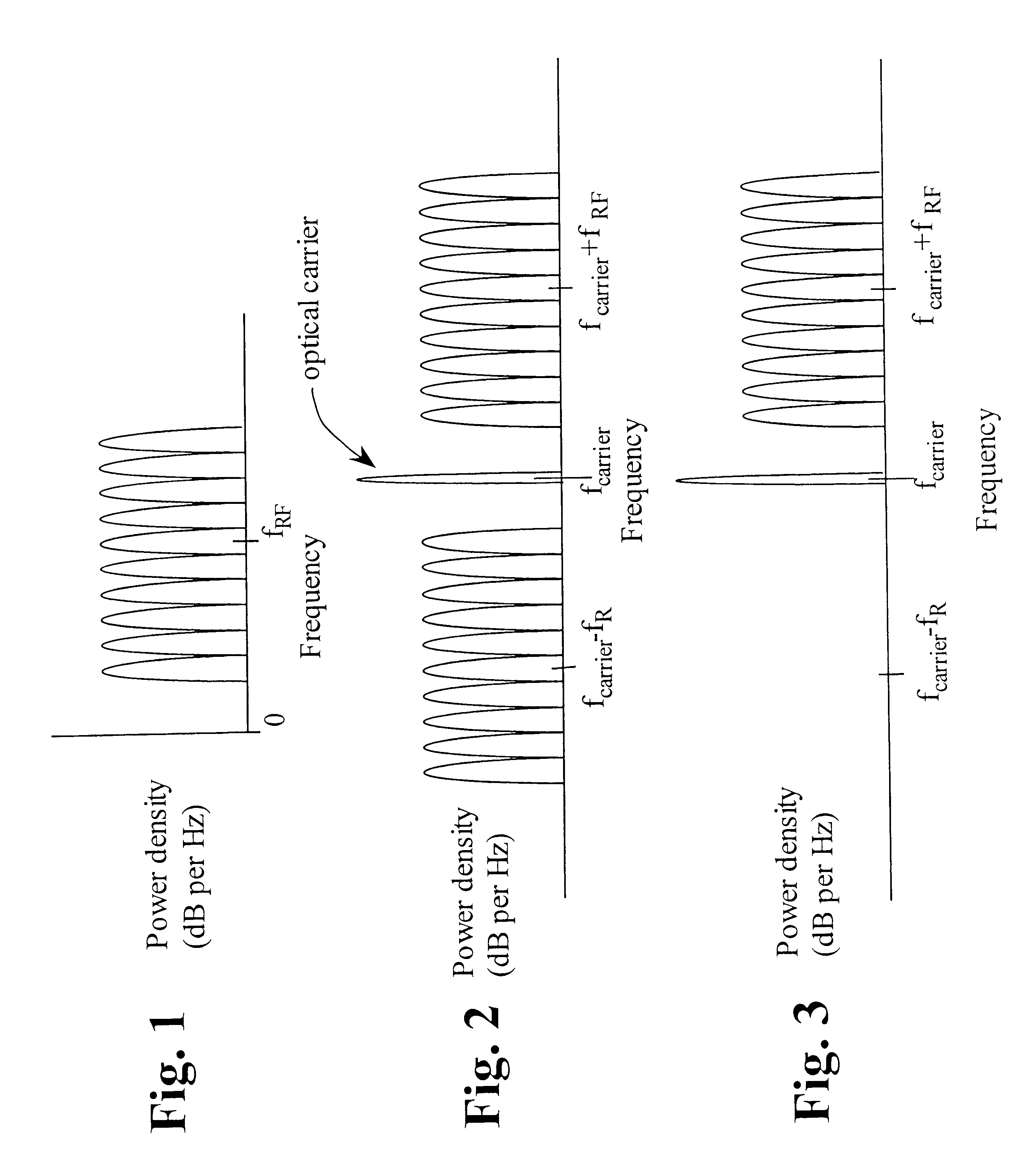
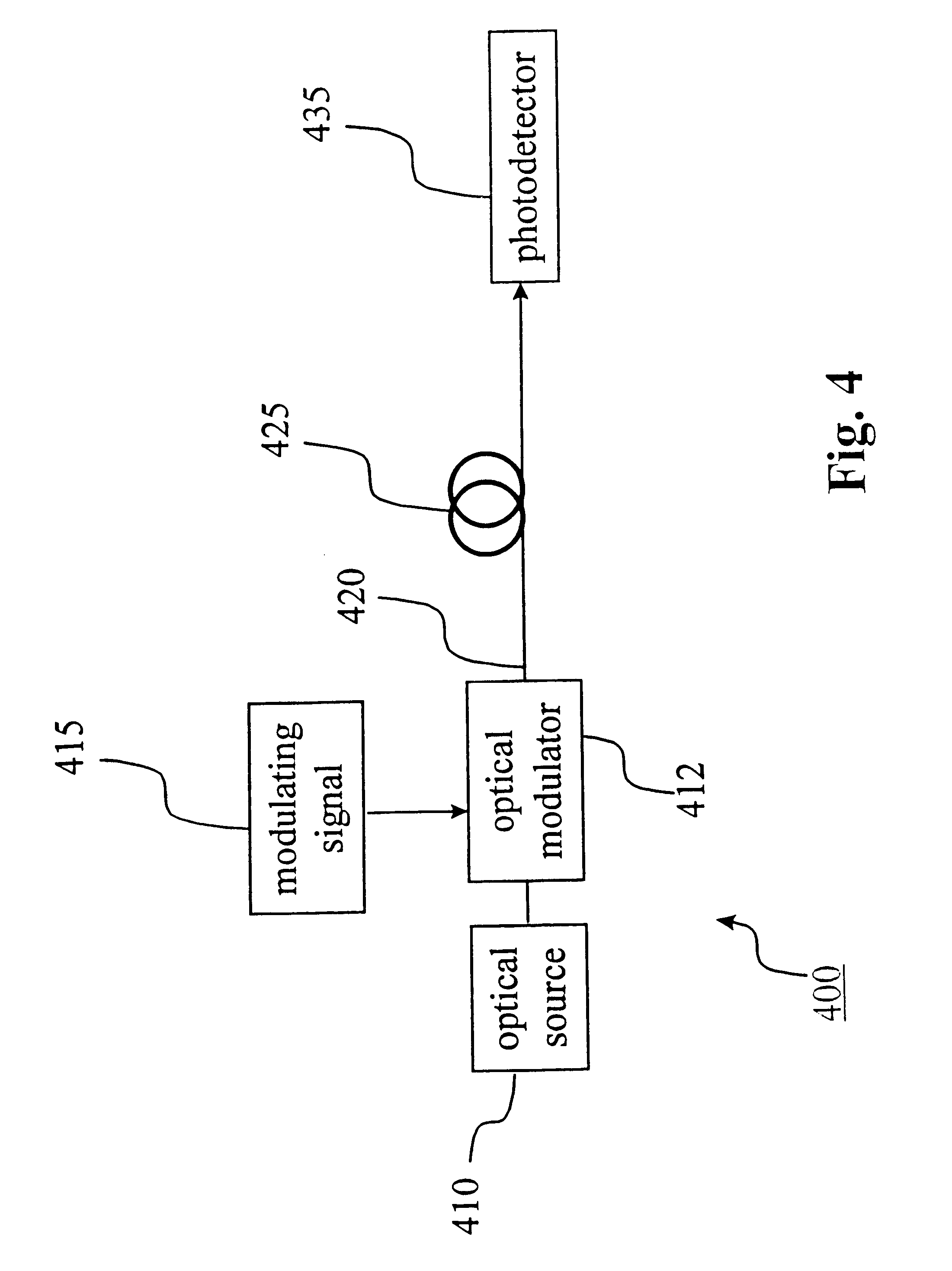
However, if the phase difference between the two optical sidebands at optical frequencies (f.sub.carrier +f.sub.RF) and (f.sub.carrier -f.sub.RF) received at the photodetector 435 is an odd multiple of .pi., the received signal from the upper sideband and the lower sideband will destructively interfere with each other, canceling out all the information power i

Method used


Image

  • Method and system for single-sideband optical signal generation and transmission
  • Method and system for single-sideband optical signal generation and transmission
  • Method and system for single-sideband optical signal generation and transmission

Examples


Embodiment Construction

The first through third exemplary embodiments of the invention provide a transmission system that use, for example, an MZ modulator, such as a commercial dual-electrode, traveling-wave modulator. As shown in FIG. 5, in accordance with the first exemplary embodiment of the invention, the transmission system 500 includes a line encoder 510, a power splitter 520, a first transform mechanism 530 and a second transform mechanism 540, a light source 550, an MZ modulator 560 and the transmission optical fiber 570. The line encoder 510 is coupled to the power splitter 520. The power splitter 520 is coupled to the first and second transform mechanisms 530 and 540. The first and second transform mechanisms are coupled to the MZ modulator 560. The modulator 560 is also coupled to the light source 550 and the transmission fiber 570.

A baseband data signal 505 is input to the system 500 and is line coded using the line encoder 510, which generates an encoded data signal 515 with little low-freque...


PUM


Abstract

A method and system for generating and transmitting optical signals with only one sideband. Single-sideband optical signal transmission reduces the signal impairment effects associated with dispersion. Such transmission also increases the spectral efficiency of optical transmission systems. Single-sideband modulation also makes possible electrical compensation for optical link dispersion during transmission. Single-sideband modulation is generated using the modulating data signal and its Hilbert transform, which is approximated by a tapped-delay time filter. Line coding is used to remove the low-frequency content in the modulating data signal, avoiding the inefficiencies of tapped-delay-line filter approximated Hilbert transformers at low frequencies. Line coding can also help optical single side band signal generation and transmission using a simple optical filter instead of Hilbert transformers.

Description

1. Field of InventionThis invention relates to a method and system for optical single-sideband data generation and transmission.2. Description of Related ArtThe ability of the Mach-Zehnder (MZ) intensity modulator to control both intensity and optical frequency has been demonstrated to improve the performance of long-haul fiber-optic systems such as those used by the telecommunications industry. See, F. Koyama and K. Iga, "Frequency chirping in external modulators," Journal of Lighwave Technology, Vol. 6, pp. 87-93, 1988. In addition, the use of high-power diode-pumped YAG lasers operating at 1300 nano-meters (nm) and MZ external intensity modulators based on LiNbO.sub.3 has found wide application in the cable TV (CATV) industry.Conventionally, optical transmission systems may use either direct or external modulation of a laser. Ideally, the intensity of the light output from a modulated laser should be linearly proportional to the injected current, and the frequency of the optical ...

Claims


Application Information

Patent Timeline
IPC IPC(8): H04B10/152H04B10/155
CPCH04B10/505H04B10/5051H04B10/58H04B10/5165H04B10/5055
Inventor GNAUCK, ALAN H.LAM, CEDRIC F.WOODWARD, SHERYL LEIGH
Owner AMERICAN TELEPHONE & TELEGRAPH CO
Why Eureka
Try Eureka