
Air driven reductant delivery system

a technology of reductant and delivery system, which is applied in the direction of positive displacement liquid engines, pumps, machines/engines, etc., can solve the problems of complex motor control system, inability to effectively remove oxidative specie nox, and limited application of this method

Active Publication Date: 2014-11-11
YAN MI +1
View PDF18 Cites 22 Cited by
  • Summary
  • Abstract
  • Description
  • Claims
  • Application Information

AI Technical Summary

Benefits of technology

The present invention is an apparatus and method for delivering reductant into an exhaust gas treatment system of an internal combustion engine. The apparatus includes a reductant supply module with an air driven hydraulic pump, a hydraulic buffer, a pressure sensor, a dosing control unit, and an injector. The apparatus has several technical effects: (i) accurate dosing rate control insensitive to pressure variations in the air supply, (ii) saving heating means for the pump, (iii) allowing the reductant pressure in the hydraulic buffer to be controlled constant, and (iv) enabling the use of a variety of compressed air sources. These technical effects enable the dosing system to use a variety of compressed air sources, including an engine turbo, leading to improved performance and efficiency of the exhaust gas treatment system.

Problems solved by technology

In lean combustion engines, due to the existence of large amount oxygen excess, passive means without extra dosing agents, such as that using a three-way catalyst, normally are not able to effectively remove the oxidative specie NOx, as that in most of spark-ignition engines.
However, due to safety concerns and difficulties in handling pure ammonia, normally urea solution is used in ammonia SCR systems.
The requirements of a continuous air flow and a precisely controlled metering pump limit the application of this method.
However, in this method, due to the requirement of pressure control, typically a liquid pump, such as a membrane pump, driven by a motor, is needed in establishing and maintaining the rail pressure, and a complex motor control system is required.
Different from reductant tank heating control, line heating is a distributed heating and it is hard and costly to use closed-loop controls.

Method used


Image

  • Air driven reductant delivery system
  • Air driven reductant delivery system
  • Air driven reductant delivery system

Examples


Embodiment Construction

Reductant Delivery System

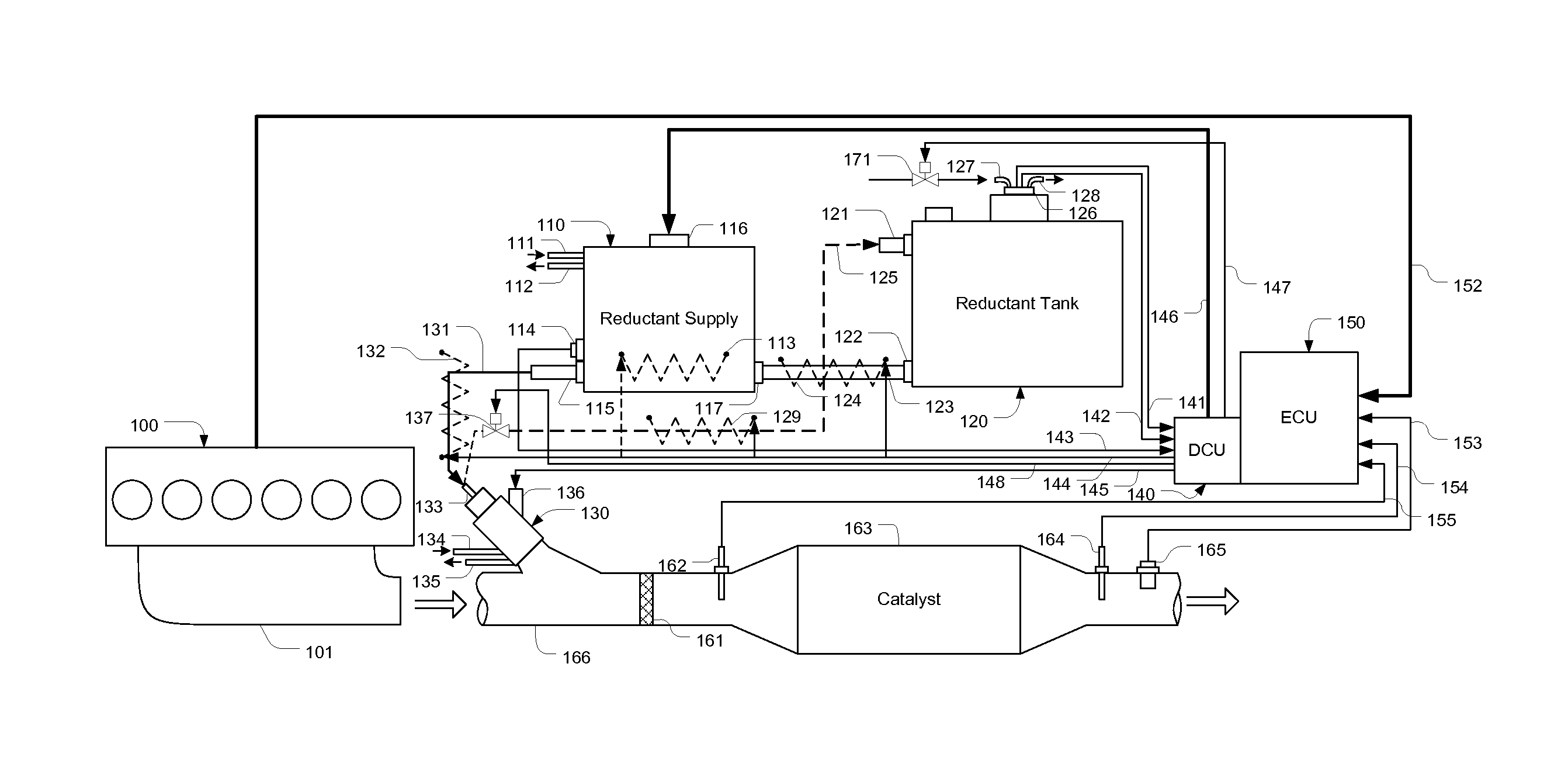
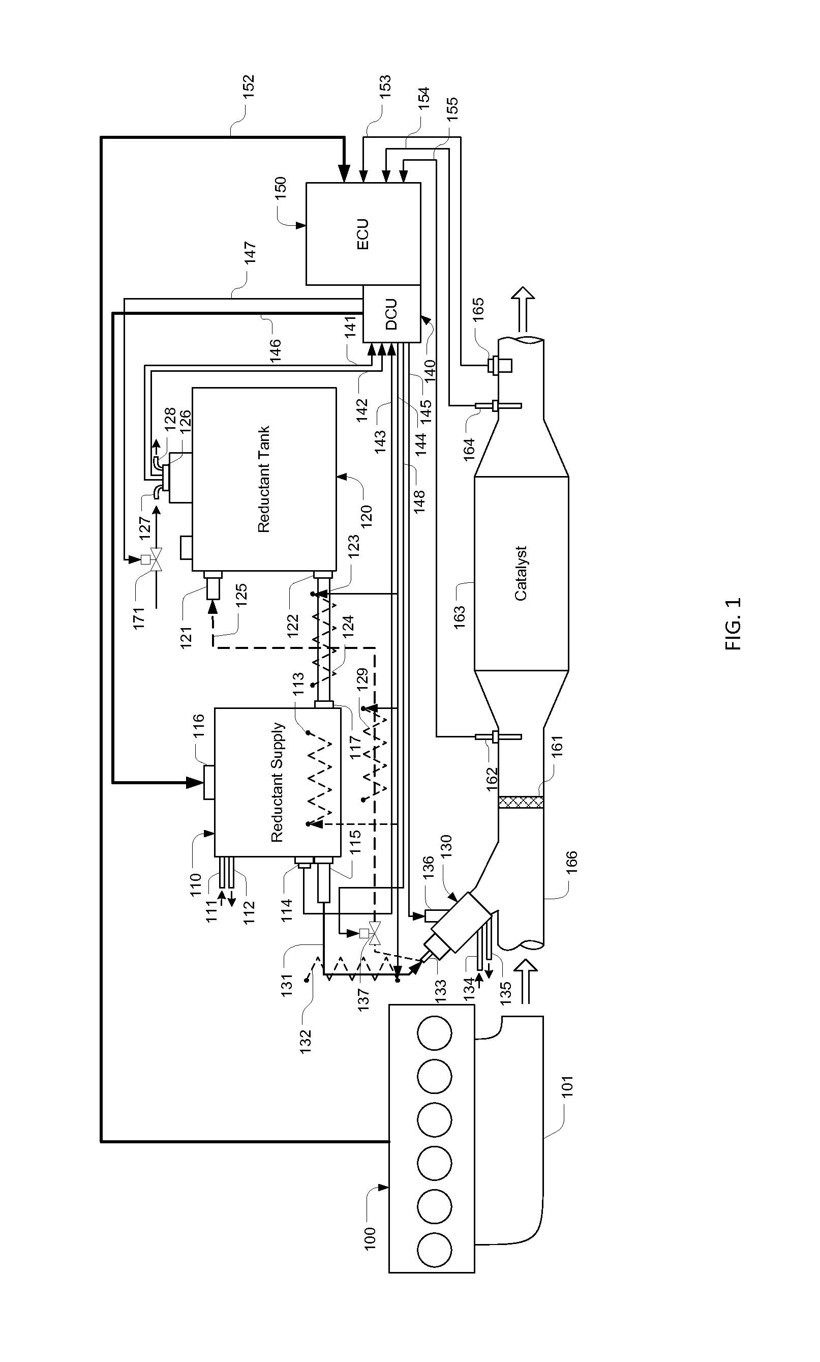
[0034]Referring to FIG. 1, in an engine aftertreatment system, exhaust gas generated by an engine 100 enters a passage 166 through a manifold 101. On the passage 166, a reductant injector 130 is installed. The solenoid valve of the injector 130 is controlled by a Dosing Control Unit (DCU) 140 through a signal line 145 connected to a port 136. And reductant is provided by a reductant supply module 110 through a pressure line 131 fluidly connected to a port 133. To avoid damages caused by high temperature exhaust gas, engine coolant is cycled from an inlet port 134 to an outlet port 135. The reductant injected from the injector 130 mixes with exhaust gas, and through a mixer 161, the result gas enters a catalyst 163, where SCR reactions reduce NOx from the exhaust gas.

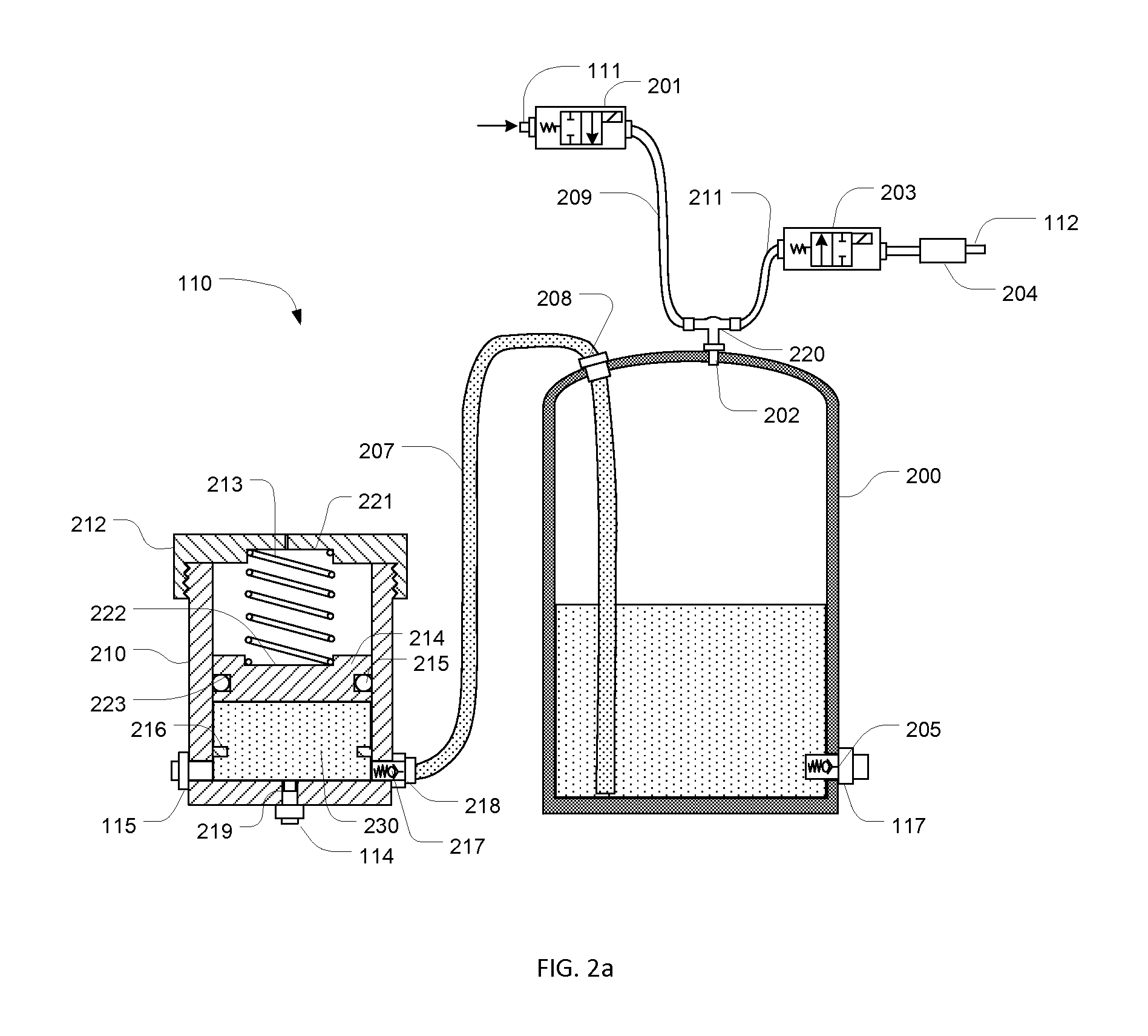
[0035]The reductant supply module 110 has a port 115 fluidly connected to the port 133 of the injector 130 with the line 131 for providing pressurized reductant supply to the injector. A pressure...


PUM


Abstract

A dosing system for delivering reductant to an exhaust gas treatment system of an internal combustion engine using air driven hydraulic pumps for closed-loop controlling reductant pressure and a two-stage PWM control method for controlling dosing rate. Reductant residue in the dosing systems is purged by using compressed air after a dosing process completes, and when the air driven hydraulic pumps are positioned inside a reductant tank, dedicated heating means for the pumps is not necessary. The air driven hydraulic pumps can also use low pressure compressed air, and the closed-loop pressure control together with the two-stage PWM control allow dosing accuracy insensitive to pressure variations in compressed air. These new features enable the dosing system use a variety of compressed air sources, including an engine turbo.

Description

[0001]This present application claims priority from U.S. provisional application No. 61 / 575,469 having the same title as the present invention and filed on Aug. 22, 2011.FIELD OF THE INVENTION[0002]The present invention relates to an apparatus and method for delivering reductant into an exhaust gas treatment system of an internal combustion engine for removing regulated species in exhaust gas, and more specifically, to an apparatus and method using air driven hydraulic pump to deliver liquid reducing agents into an exhaust gas treatment system of an internal combustion engine.BACKGROUND OF THE INVENTION[0003]Environmentally harmful species in the exhaust gas emitted from an internal combustion engine, such as hydrocarbons (HC), carbon monoxide (CO), particulate matters (PM), and nitric oxides (NOx) are regulated species that need to be removed from the exhaust gas. In lean combustion engines, due to the existence of large amount oxygen excess, passive means without extra dosing agen...

Claims


Application Information

Patent Timeline
Patent Type & Authority Patents(United States)
IPC IPC(8): F01B3/00
CPCF01N9/00F01N3/08F04B9/12F01N3/20F01N3/28F04B13/00F01N2610/1433F01N2900/1808Y10T137/0379F01N2900/1811F01N2610/144F01N2610/1493F01N2610/02F01N2610/146F01N3/2066F01N2900/1814F01N2610/03F02B37/164Y02T10/12
Inventor YAN, MIQI, BAOHUA
Owner YAN MI
Learn More