
Device and method for welding profiled parts

a technology for profiled parts and devices, applied in the direction of mechanical control devices, process and machine control, instruments, etc., can solve the problems of reducing fracture values, affecting the appearance, and no information as to how research findings can be used in actual practice, so as to reduce the total production time, reduce the effect of softening and joining times and reducing the number of times

Active Publication Date: 2014-11-11
ROTOX HLDG GMBH & CO KG
View PDF6 Cites 0 Cited by
  • Summary
  • Abstract
  • Description
  • Claims
  • Application Information

AI Technical Summary

Benefits of technology

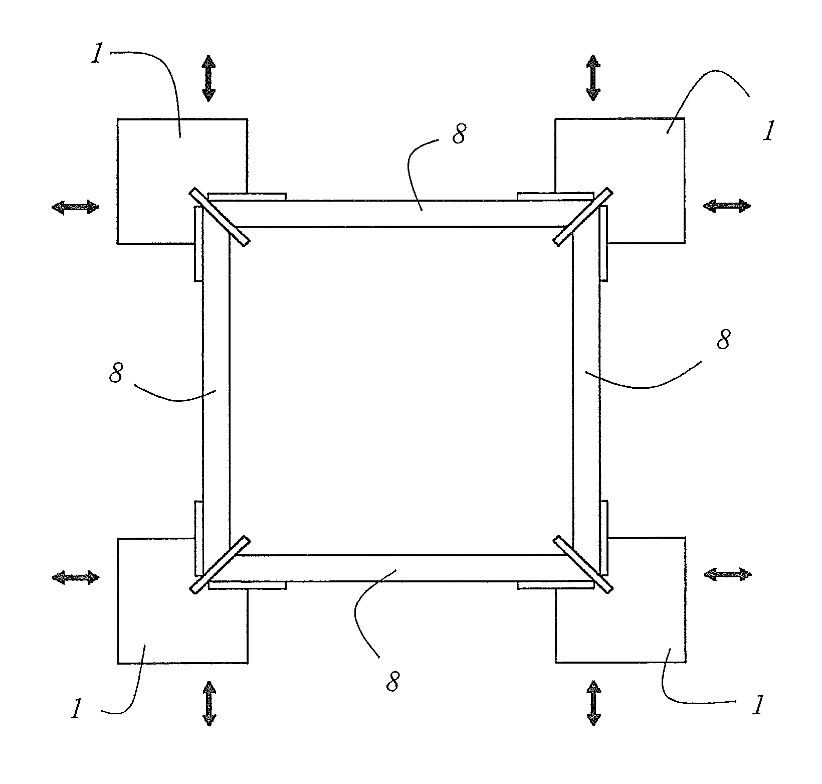
[0021]It has been recognized that allowing slight dimensional tolerances—at least prior to the welding process—yields very considerable advantages for the product that is to be created by means of welding, particularly in terms of the softening and joining times as well as in terms of the risk of undesired material changes. For example, during the manufacture of window or door frames, deviations of the outer dimensions of the frame amounting to about 0.5 mm—in view of a gap dimension of about 12 mm between the leaf and door frames—can be accepted without any problem without this translating into technical limitations in the function or usability of the windows or doors. However, the softening and joining times can be drastically reduced (while attaining approximately the same or sometimes greater strength of the joint thus created). As a result, the total production time is shortened, so that within the same unit of time, a larger number of window or door frames can be manufactured.
[0022]In a particularly advantageous embodiment, which is described in detail further below, however, the dimensional tolerances initially allowed during the welding process can also be eliminated or at least reduced. Consequently, this embodiment entails a two-fold advantage, namely, the ability to produce more quickly and more efficiently on the one hand, and a high level of dimensional precision on the other hand.
[0023]In an advantageous embodiment of the device according to the invention, the welding head and / or a part of the welding head, but at least one heating element of the welding head for softening the profiled parts, especially a heat reflector, can be automatically positioned within a spatial tolerance area around the target welding position—preferably within the support plane. According to the invention, it can particularly be provided that the device has a compensation device that positions or moves the welding head and / or the part of the welding head within a spatial tolerance area around the target welding position as a function of at least one dimensional deviation displayed by at least one of the profiled parts. An especially advantageous embodiment is one in which the compensation device automatically or autonomously undertakes the positioning within the tolerance area. When the device according to the invention is used, smaller size allowances are possible than the size allowances necessary when the devices known from the state of the art are used. Accordingly, considerably shorter softening times or equalization times are needed. Advantageously, softening times are made possible that are so short (a few seconds) that the ends of the profiled parts can be heated up without material changes, even when the heat reflector is at higher temperatures, something which is virtually impossible without undesired material changes at the softening times known from the state of the art.
[0025]Hence, it is possible to largely prevent the drawback associated with the methods and devices known from the state of the art, namely, that the ends of the profiled parts that are to be welded to each other each undergo a different softening process. In an advantageous manner, it is especially prevented that one end of the profiled part is already in contact with the heat reflector while the end of the profiled part to be welded to the end of the first profiled part is still on its way to the heat reflector—for instance, because of a larger initial distance—and / or it is prevented that one end of the profiled part is still in contact with the heat reflector while the end of the profiled part that is to be welded to the end of the first profiled part has already moved away from the heat reflector. As described, according to the invention, it is possible to effectively avoid the situation that occurs with the methods and devices known from the state of the art, namely, that one end of the profiled part is in contact with the heat reflector longer than necessary because, to a certain extent, there is a need to wait until the end of the profiled part that is to be welded to the end of the first profiled part has already softened as well.
[0030]In a special embodiment, a positioning unit is provided with which the welding head or the part of the welding head is first placed in the target welding position and subsequently, for example, during the joining process, it is positioned within the tolerance area especially by controlling and / or regulating the drives. However, it can also be provided that the positioning unit is moved to a target welding position, while, at the same time, a fine positioning is carried out within the tolerance area. In both variants, it can be advantageously provided that the welding head and / or the part of the welding head, but at least one heating element of the welding head for softening the profiled parts, especially a heat reflector, is mounted—especially resiliently—so as to be movable within the tolerance area relative to the positioning unit.
[0042]The force that acts on the welding head or on the part of the welding head during the welding process in order to reduce and / or eliminate dimensional deviations displayed by the profiled parts can be applied, for instance, pneumatically and / or hydraulically and / or by means of a spindle system. In particular, a preferably electronic control unit can be provided that switches off the acting force when the target position has been reached and / or that already reduces the acting force when the target position is being approached. In a simple and yet reliable and dependable embodiment, it is provided that the target position is determined by means of one or more mechanical stops and that the force moves the welding head or the part of the welding head during the welding until the stop or the stops has / have been reached, thus preventing the welding head from being moved further beyond the target position.

Problems solved by technology

As of now, however, there is no information as to how these research findings can be employed in actual practice.
In this context, it can happen that, when high heat-reflector temperatures are used, the material undergoes a change, especially decomposition or burning, which can ultimately have a detrimental effect on the appearance and lead to reduced fracture values.
The risk of such undesired changes is greater the longer the time of exposure to heat and the higher the temperature.
Allowing such dimensional deviations by using a profile stop that is movable or a profile stop whose thickness can be varied, however, has the drawback that the profiled parts are arranged offset and / or asymmetrically with respect to the welding head, especially with respect to the heat reflector of the welding head.
This entails the additional disadvantage that the ends of the profiled parts that are to be welded to each other undergo a different softening process.
This gives rise to welds with reduced strength values.

Method used


Image

  • Device and method for welding profiled parts
  • Device and method for welding profiled parts
  • Device and method for welding profiled parts

Examples


Embodiment Construction

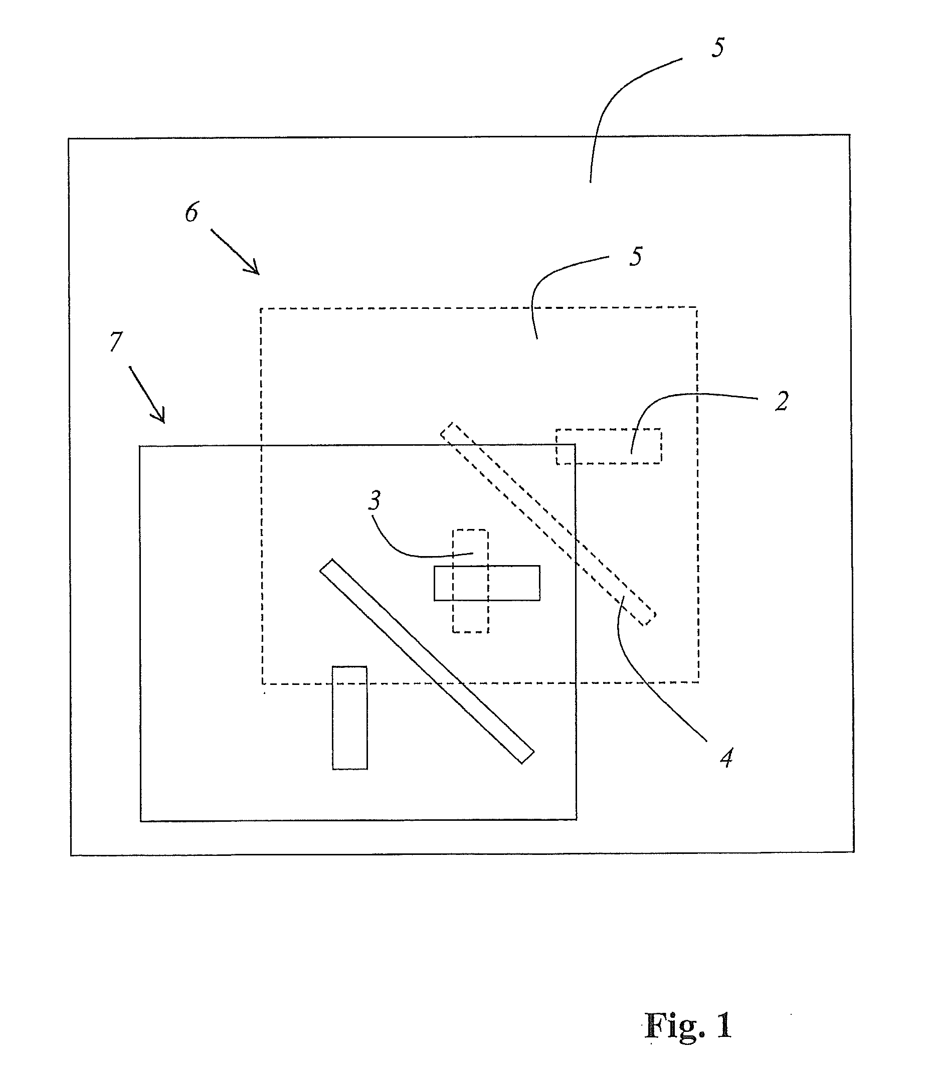
[0059]FIG. 1 shows the mode of operation of a device according to the invention, on a welding head 1. For the sake of clarity, the welding heads shown are only depicted schematically, with two profile contacts 2, 3 and one profile stop 4. In the case of the devices known from the state of the art, the welding head 1 is positioned in a target welding position shown by a broken line in the figure, and this is done completely independently of dimensional deviations displayed by the profiled parts that are to be welded. In contrast to this, with the device according to the invention, the welding head 1 (and / or parts of the welding head) are positioned within a spatial tolerance area 5 around the target welding position 6 (broken line) as a function of at least one dimensional deviation from a target dimension displayed by at least one of the profiled parts that is to be welded (not shown here). The actual positioning 7 within the tolerance area 5 is shown by a solid line. The positionin...


PUM

PropertyMeasurementUnit
lengthaaaaaaaaaa
timeaaaaaaaaaa
lengthaaaaaaaaaa

Abstract

The invention relates to a device for welding profiled parts (8), in particular plastics profiled parts, having at least one welding head (1) that can be positioned in a predetermined or predeterminable target welding position (6) relative to another welding head (1, 9) and / or relative to a holding device. According to the invention the welding head (1) and / or a part of the welding head (1), that comprises at least one heating element, such as a heating plate, for melting the profiled parts, can be positioned and / or is movable in accordance with at least one dimensional variation of at least one of the profiled parts (8) from a target dimension in a spatial tolerance range (5) around the target welding position (6).

Description

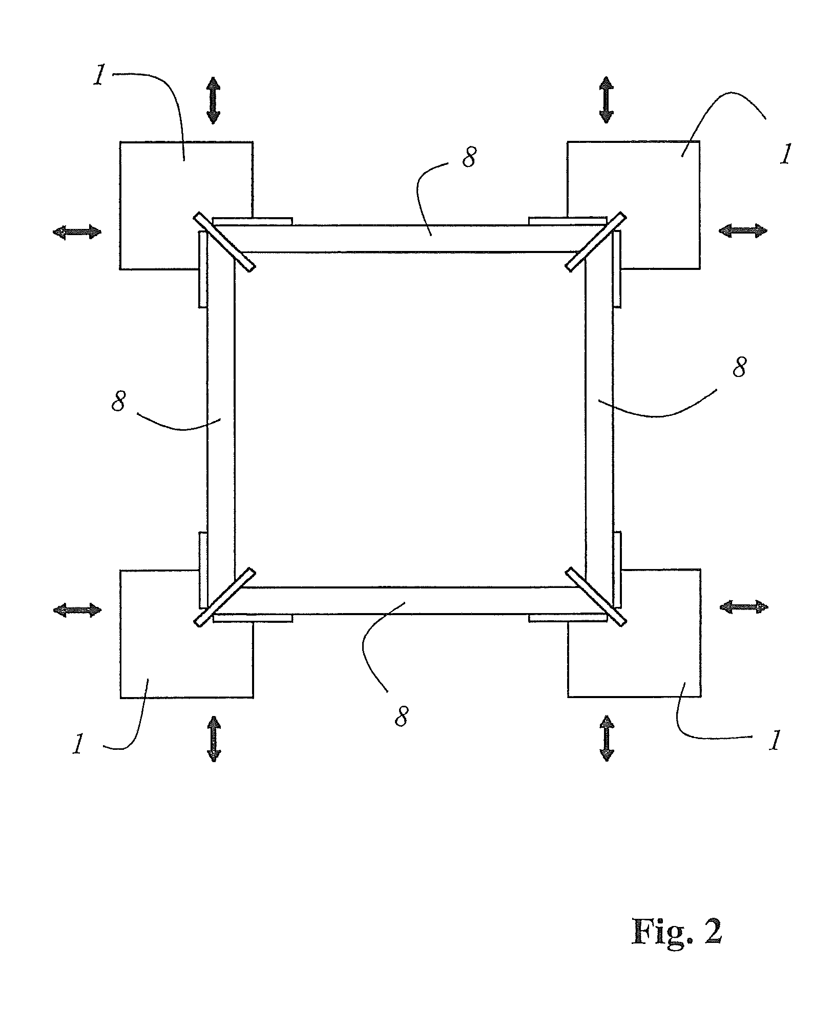
CROSS-REFERENCE TO RELATED APPLICATIONS[0001]This application is a national stage application (under 35 U.S.C. §371) of PCT / EP2011 / 051396, filed Feb. 1, 2011, which claims benefit of German application 10 2010 012 359.5, filed Mar. 22, 2010.TECHNICAL FIELD AND STATE OF THE ART[0002]The invention relates to a device for welding profiled parts, especially plastic profiled parts, comprising at least one welding head that can be positioned in a pre-specified or pre-specifiable target welding position relative to another welding head and / or relative to a holding device.[0003]The invention also relates to a method for welding profiled parts, especially plastic profiled parts.[0004]Devices of the above-mentioned type are used especially for welding PVC profiles in order to form window frames or door frames. Such a device is disclosed, for example, in German patent application DE 195 06 236 A1. This device has four welding heads for purposes of simultaneously producing the four corner joint...

Claims


Application Information

Patent Timeline
Patent Type & Authority Patents(United States)
IPC IPC(8): B32B37/00B29L31/00B29C65/20B29C65/00
CPCB29C66/8163B29L2031/005B29C65/00B29C66/9241B29C66/52431B29C66/9674B29C66/8161B29C66/843B29C66/8223B29C66/92B29C66/92651B29C66/95B29C66/8748B29K2027/06B29C66/1162B29C66/92311B29C65/203B29C66/71B29C66/8412B29C66/8242B29C66/961Y10T156/17B29C65/7841
Inventor EISENBACH, BERNDSCHMITT, HANS
Owner ROTOX HLDG GMBH & CO KG
Learn More