Computer arrangement for and method of matching location data of different sources

a technology of location data and computer arrangement, applied in the field of matching location data, can solve the problems of bringing a cost of many thousands of man hours for mapping these two sources for an average city, unacceptable levels of quality in the matching process, and requiring significant human interaction in the current process, so as to achieve the effect of reducing human interaction

Active Publication Date: 2014-11-11
TOMTOM GLOBAL CONTENT
View PDF14 Cites 4 Cited by
  • Summary
  • Abstract
  • Description
  • Claims
  • Application Information

AI Technical Summary

Benefits of technology

[0010]Thus, the system and method as claimed in their broadest context may be used in a process of automatic synchronization, or position matching, between the first and third sources, as referred to in the introduction above, using laser scanner data. In an embodiment, the second and third sources are located on an MMS system, and the first source is an aerial photograph. Then, in effect, the relative position error between the MMS picture and the building derived from the aerial photograph can be eliminated or dramatically reduced.
[0012]By applying the system and method according to the invention, the human interaction can be reduced by a factor as high as 95%.

Problems solved by technology

However, currently used processes may require significant human interaction to have the required correlation between these two sources.
The speed of manual matching may be on average 2 km / h which in total would bring a cost of many thousands man hours for mapping these two sources for an average city.
To achieve an industrial process with an acceptable level of quality, the maximum positional deviation between both sources should be less than 0.5 m. However, typical positional accuracies associated with these separate sources are not below 1 m, which may result in unacceptable levels of quality in the matching process.

Method used


Image

  • Computer arrangement for and method of matching location data of different sources
  • Computer arrangement for and method of matching location data of different sources
  • Computer arrangement for and method of matching location data of different sources

Examples


Embodiment Construction

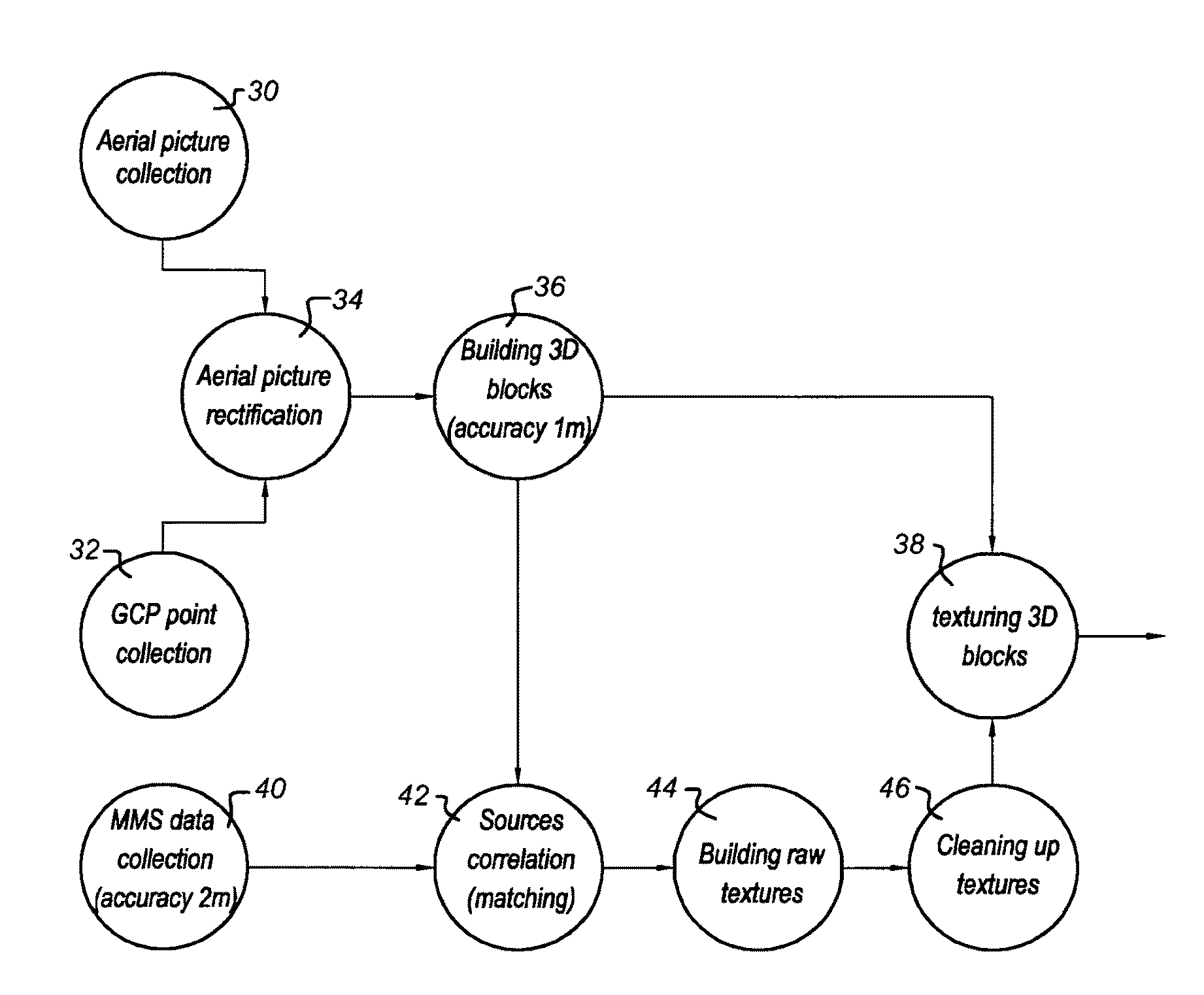
[0032]The invention will be explained with reference to pictures of building block façades as obtained by cameras on an MMS system, footprints of those building blocks as obtained from aerial pictures and laser scan samples as obtained from laser scanners on the MMS system. However, the idea of matching location data of different sources while using laser samples has a larger implementation capability than just this context.

[0033]In an embodiment of the invention, building block façade data as obtained by one or more cameras on a mobile mapping system (MMS) is processed. Moreover, laser scan data as obtained by one or more laser scanners on such a MMS system may be used.

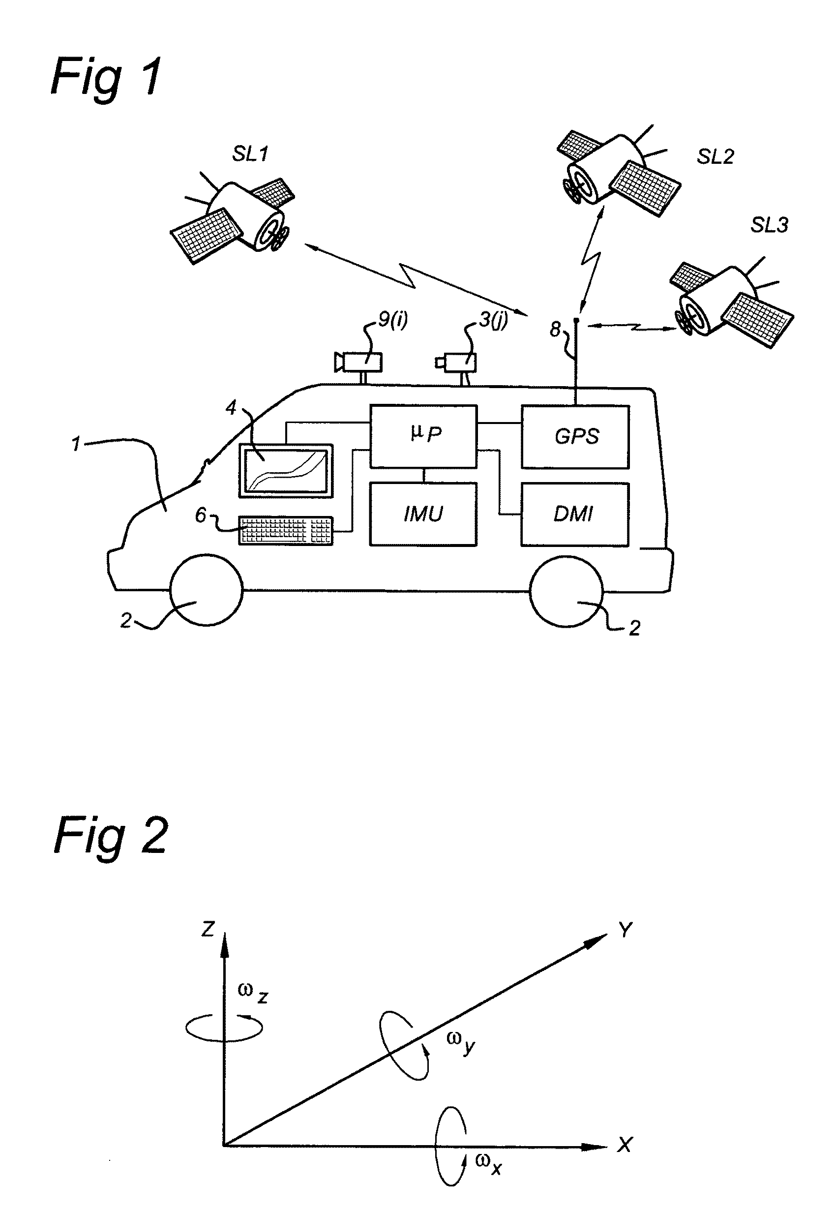
[0034]FIG. 1 shows a MMS system that takes the form of a car 1. The car 1 is provided with one or more cameras 9(i), i=1, 2, 3, . . . I, and one or more laser scanners 3(j), j=1, 2, 3, . . . J. The car 1 can be driven by a driver along roads of interest.

[0035]The car 1 is provided with a plurality of wheels 2. Moreov...


PUM


Abstract

A computer arrangement is disclosed, including a processor and a memory that stores a computer program, object data originating from a first source and including object location data, and laser samples originating from a second source, including a sub-set of laser samples relating to the object and including laser sample location data as to each laser sample. In at least one embodiment, the processor compares the object location data and the laser sample location data of the sub-set of laser samples, and matches the object location data to the laser sample location data of the sub-set of laser samples based on this comparison, and thereby corrects for relative positional errors between the first and second sources of location data. The object may be a building façade, for example.

Description

FIELD OF THE INVENTION[0001]The present invention relates to matching location data of building block façades to façade location data derived from laser scanners on a geo-positioned mobile mapping system. The laser scanners may be 2D rotating but the field of application is not restricted hereto.PRIOR ART[0002]Systems for and methods of matching location data of building block façades which originate from a source, like cameras on a mobile mapping system, to façade location data originating from an other source like aerial images are known from the prior art. Likewise, it is known to detect texture elements in the building block façades and to replace them by standard texture elements such that only a few of these standard texture elements need be stored in a memory, thus saving memory space.[0003]However, currently used processes may require significant human interaction to have the required correlation between these two sources. The speed of manual matching may be on average 2 km / ...

Claims


Application Information

Patent Timeline
Patent Type & Authority Patents(United States)
IPC IPC(8): G01C21/28G01C11/02G06T15/10
CPCG01C11/02G01C21/28
Inventor KMIECIK, MARCIN MICHALNOWAK, WOJCIECH TOMASZ
Owner TOMTOM GLOBAL CONTENT
Why Eureka
Try Eureka