Ink-jet recording apparatus

a recording apparatus and inkjet technology, applied in the direction of printing mechanism, spacing mechanism, printing, etc., can solve the problem of difficult to prevent the complete decline of throughput in the recording process, and achieve the effect of reducing the number of flushing processes, preventing the decline of throughput in the recording process, and maintaining the throughput of the recording process

Active Publication Date: 2014-11-18
BROTHER KOGYO KK
View PDF6 Cites 0 Cited by
  • Summary
  • Abstract
  • Description
  • Claims
  • Application Information

AI Technical Summary

Benefits of technology

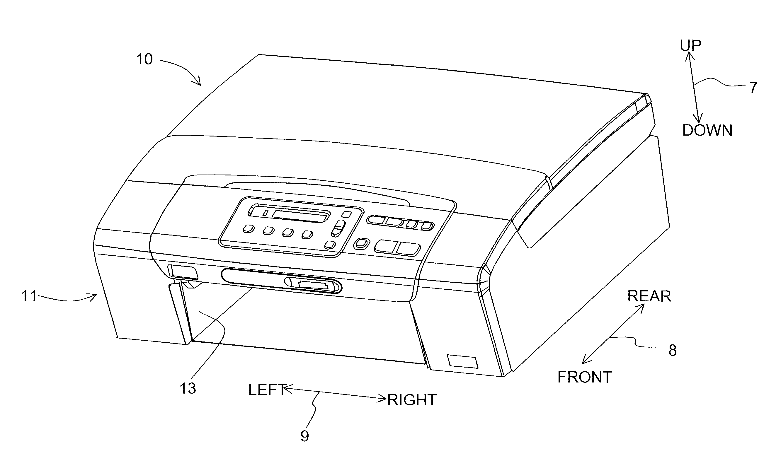
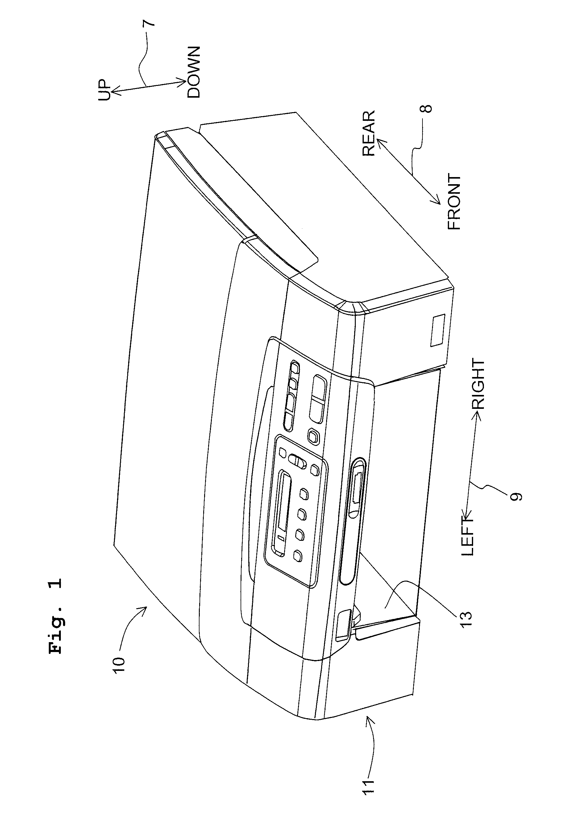
[0007]The present teaching has been made taking the foregoing circumstances into consideration, an object of which is to provide an ink-jet recording apparatus which allows ink discharged from nozzles to reliably land in an ink receiving section while suppressing a decline of throughput of image recording.
[0009]According to the above configuration, since the flushing process is executed during the acceleration process, it is possible to suppress the decline of throughput in the recording process. However, even when the flushing process is executed during the acceleration process, it is difficult to prevent the decline of throughput in the recording process completely. In view of this, by determining the number of nozzle groups, for which the flushing operations are performed in one flushing process, depending on acceleration of the carriage, the discharged ink can be reliably landed in the ink receiver while maintaining the throughput of the recording process.
[0010]In particular, in a case that the acceleration of the carriage in the acceleration process is small, the number of nozzle groups selected in the selecting process is increased to decrease the number of flushing processes. Accordingly, the decline of throughput in the recording process can be suppressed. On the other hand, in a case that the acceleration of the carriage in the acceleration process is great, the number of nozzle groups selected in the selecting process is decreased. Accordingly, the ink discharged in the flushing process can be reliably landed in the ink receiving section.

Problems solved by technology

However, in a case that the flushing operation is performed during the process of accelerating the carriage as described above and that acceleration of the carriage is great, there is a possibility that a part of the ink discharged from the nozzles is not landed in the ink receiving section.
This problem is especially conspicuous when the ink receiving section is narrow with downsizing of the ink-jet recording apparatus.
However, even when the flushing process is executed during the acceleration process, it is difficult to prevent the decline of throughput in the recording process completely.

Method used


Image

  • Ink-jet recording apparatus
  • Ink-jet recording apparatus
  • Ink-jet recording apparatus

Examples


first embodiment

[Operation and Effect of First Embodiment]

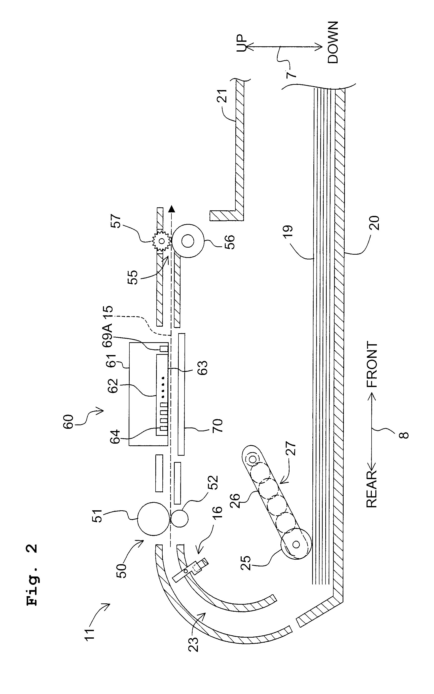
[0081]According to the first embodiment, in a case that the acceleration of the carriage 61 in the acceleration section is great (that is, the quality is low), the number of nozzle groups 64 for which the flushing operations are performed in one flushing process is decreased. Accordingly, the ink discharged from each of the nozzle groups 64 can be landed in the waste ink tray 80 reliably. On the other hand, in a case that the acceleration of the carriage 61 in the acceleration section is small (that is, the quality is high), the number of nozzle groups 64 for which the flushing operations are performed in one flushing process is increased. Accordingly, the number of flushing processes can be decreased. That is, the throughput of the recording process can be maintained and further the discharged ink can be landed in the waste ink tray 80 reliably.

[0082]In the first embodiment, since the nozzle group for which the flushing operation is perform...

second embodiment

[Second Embodiment]

[0085]Subsequently, an explanation will be made about an image recording process according to the second embodiment with reference to FIGS. 11 to 14. The explanation of common parts between the first and second embodiments is omitted, and differences between the first and second embodiments will be explained in detail. The image recording process of the second embodiment is different from that of the first embodiment in that the number of nozzle groups 64 for which the flushing operations are performed in one flushing process can be changed during the image recording on one recording paper sheet 19.

[0086]At first, the controller 130 determines only the recording velocity depending on the image quality in an operation method determining process shown in FIGS. 11A and 11B (S81). That is, in the operation method determining process shown in FIG. 7, in a case that the image quality is the first quality (S51: Yes), the controller 130 selects the first recording velocit...


PUM


Abstract

An ink jet recording apparatus includes: a carriage which is movable in a forward direction from one end to the other end; a recording head provided in the carriage and having a plurality of nozzle groups from which the ink is discharged; an ink receiver provided at a side of the one end including a flushing position and configured to receive the ink discharged by a flushing operation; and a controller configured to control operations of the carriage and the recording head. In a case that the carriage is moved in the forward direction, the controller executes: an acceleration process for accelerating the carriage; a selecting process for selecting at least one nozzle group for which the flushing operation is performed; a flushing process for performing the flushing operation for the nozzle group selected in the selecting process during the acceleration process; and a recording process for recording the image.

Description

CROSS REFERENCE TO RELATED APPLICATION[0001]The present application claims priority from Japanese Patent Application No. 2012-283340, filed on Dec. 26, 2012, the disclosure of which is incorporated herein by reference in its entirety.BACKGROUND OF THE INVENTION[0002]1. Field of the Invention[0003]The present invention relates to an ink-jet recording apparatus.[0004]2. Description of the Related Art[0005]There has conventionally been an ink-jet recording apparatus in which a flushing operation is performed by a recording head in a flushing area. The flushing area is positioned outside a recording area in which an image is recorded on a sheet, and further an ink receiving section is arranged in the flushing area. The flushing operation is an operation in which an ink is discharged from nozzles to the ink receiving section in a state that the recording head is positioned in the flushing area. Also, there has been an ink-jet recording apparatus in which the flushing operation is perform...

Claims


Application Information

Patent Timeline
Patent Type & Authority Patents(United States)
IPC IPC(8): B41J23/00B41J2/165
CPCB41J19/202B41J2/16526
Inventor KOBAYASHI, ISAO
Owner BROTHER KOGYO KK
Why Eureka
Try Eureka