Luminous keyboard and light guide plate module thereof

a technology of light guide plate and keyboard, which is applied in the field of luminous keyboard with an illumination function, can solve the problems of easy vision impairment of users, impeded operation of the dim environment of the keyboard, and inconvenient use of the keyboard, etc., and achieves the effect of improving light utilization efficiency

Active Publication Date: 2014-11-18
PRIMAX ELECTRONICS LTD
View PDF6 Cites 23 Cited by
  • Summary
  • Abstract
  • Description
  • Claims
  • Application Information

AI Technical Summary

Benefits of technology

[0009]The present invention relates to a luminous keyboard, and more particularly to a luminous keyboard with enhanced light utilization efficiency.

Problems solved by technology

In other words, the dim environment becomes hindrance from operating the keyboard.
In addition, if the numbers and the characters marked on the keys of the keyboard are reluctantly viewed in the dim environment, the user is readily suffered from vision impairment.
However, the conventional luminous keyboard 1 still has some drawbacks.

Method used


Image

  • Luminous keyboard and light guide plate module thereof
  • Luminous keyboard and light guide plate module thereof
  • Luminous keyboard and light guide plate module thereof

Examples


first embodiment

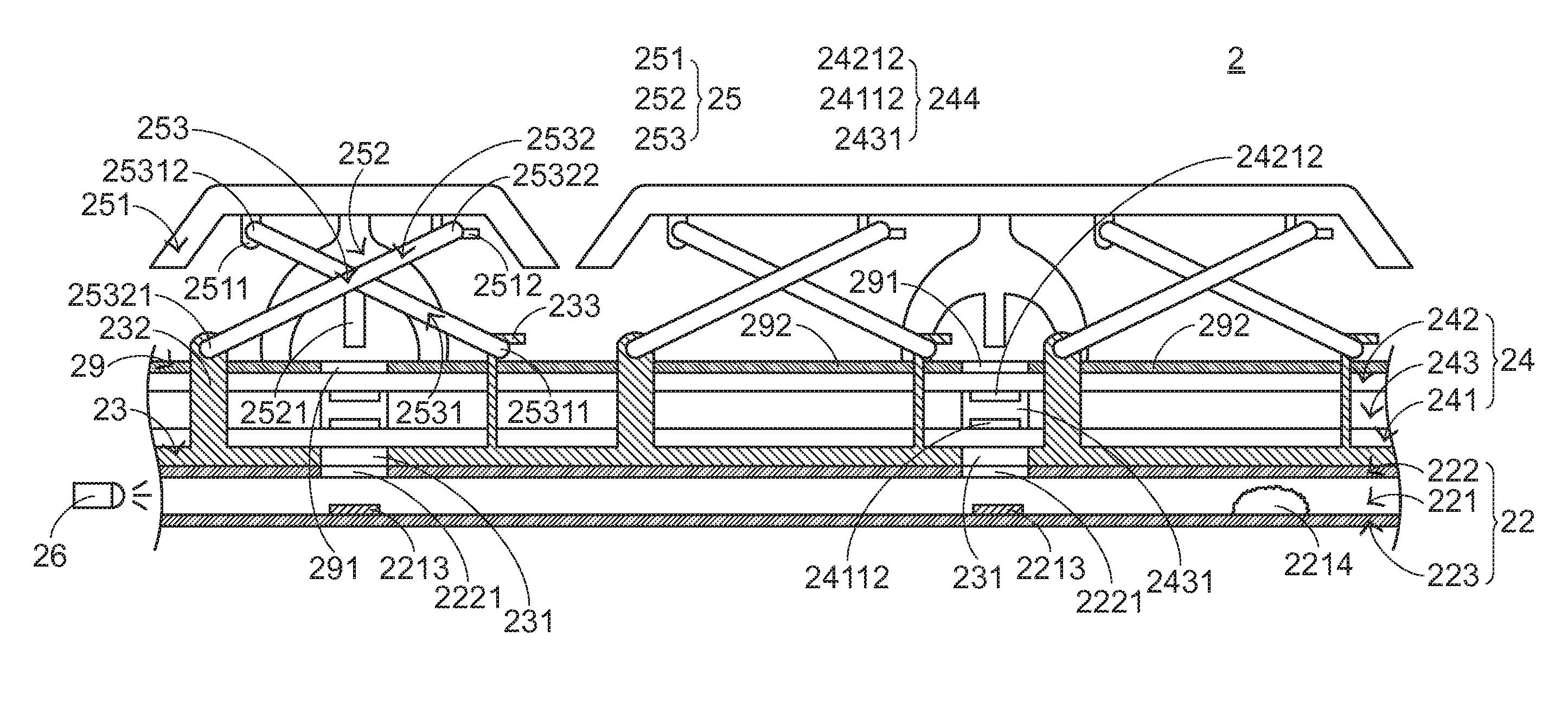
[0024]Please refer to FIGS. 4-6. FIG. 4 is a schematic side view illustrating a luminous keyboard according to the present invention. FIG. 5 is a schematic perspective view illustrating a membrane wiring board and a keyboard circuit board of the luminous keyboard of FIG. 4. FIG. 6 schematically illustrates optical paths within a light guide plate module of the membrane wiring board of the luminous keyboard of FIG. 4. From bottom to top, a light guide plate module 22, a metallic supporting plate 23, a membrane wiring board 24, a fixing layer 29 and plural keys 25 of the luminous keyboard 2 are sequentially shown. The luminous keyboard 2 further comprises a light-emitting element 26. The light-emitting element 26 is located at a lateral side of the light guide plate module 22. In this embodiment, the light-emitting element 26 is a light emitting diode, but is not limited thereto.

[0025]The membrane wiring board 24 comprises a lower wiring plate 241 and an upper wiring plate 242. A firs...

second embodiment

[0035]Those skilled in the art will readily observe that the light diffusion structure 2214 embedded downwardly into the light-guiding layer 221 and having a specified thickness may be applied to the luminous keyboards of the following embodiments while retaining the teachings of the present invention.

[0036]FIG. 8 is a schematic side view illustrating a luminous keyboard according to a third embodiment of the present invention. Except for the following items, the assembled structures of the luminous keyboard 2″ of this embodiment are substantially identical to those of the luminous keyboard 2 of the first embodiment, and are not redundantly described herein. In comparison with the luminous keyboard 2 of the first embodiment, the light guide plate module 22″ of the luminous keyboard 2″ of this embodiment is directly used as the lower wiring plate of the membrane wiring board 24″. That is, the first circuit pattern is directly formed on the light guide plate module 22″. Under this cir...


PUM


Abstract

A luminous keyboard includes a light-emitting element, a membrane wiring board, plural keys, and a light guide plate module. The plural keys are used for correspondingly triggering the plural membrane switches. The light-emitting element is used for providing the light beam to the luminous keyboard. The light guide plate module includes a first reflective layer, a second reflective layer, and a light-guiding layer between the first reflective layer and the second reflective layer. The light-guiding layer includes plural light-outputting regions and a spacing region. The plural light-outputting regions are aligned with the plural keys, respectively. The spacing region is arranged around the plural light-outputting regions. Moreover, plural light-guiding dots are located at the plural light-outputting regions, and at least one light diffusion structure is located at the spacing region.

Description

FIELD OF THE INVENTION[0001]The present invention relates to a keyboard, and more particularly to a luminous keyboard with an illuminating function.BACKGROUND OF THE INVENTION[0002]Recently, with the increasing development of information industries, portable information devices such as notebook computers, mobile phones or personal digital assistants are widely used in many instances. In case that a portable information device is used in a dim environment, the numbers and the characters marked on the keys of the keyboard of the portable information device are not clearly visible. In other words, the dim environment becomes hindrance from operating the keyboard. In addition, if the numbers and the characters marked on the keys of the keyboard are reluctantly viewed in the dim environment, the user is readily suffered from vision impairment. For solving these drawbacks, a luminous keyboard has been introduced into the market. The luminous keyboard can be used in the dim environment in ...

Claims


Application Information

Patent Timeline
Patent Type & Authority Patents(United States)
IPC IPC(8): H01H13/83F21V8/00
CPCG02B6/0011G02B6/0036G02B6/0041G02B6/0055G06F3/0202H01H2219/062
Inventor CHEN, BO-AN
Owner PRIMAX ELECTRONICS LTD
Why Eureka
Try Eureka