Combustor crossfire tube

a technology of crossfire tube and combustion chamber, which is applied in the direction of machines/engines, mechanical equipment, lighting and heating apparatus, etc., can solve the problems of overall combustion temperature, higher nitrogen oxide, other types of undesirable emissions, etc., and achieve the effect of reducing the wake of the air flow

Inactive Publication Date: 2014-11-25
GENERAL ELECTRIC CO
View PDF14 Cites 2 Cited by
  • Summary
  • Abstract
  • Description
  • Claims
  • Application Information

AI Technical Summary

Benefits of technology

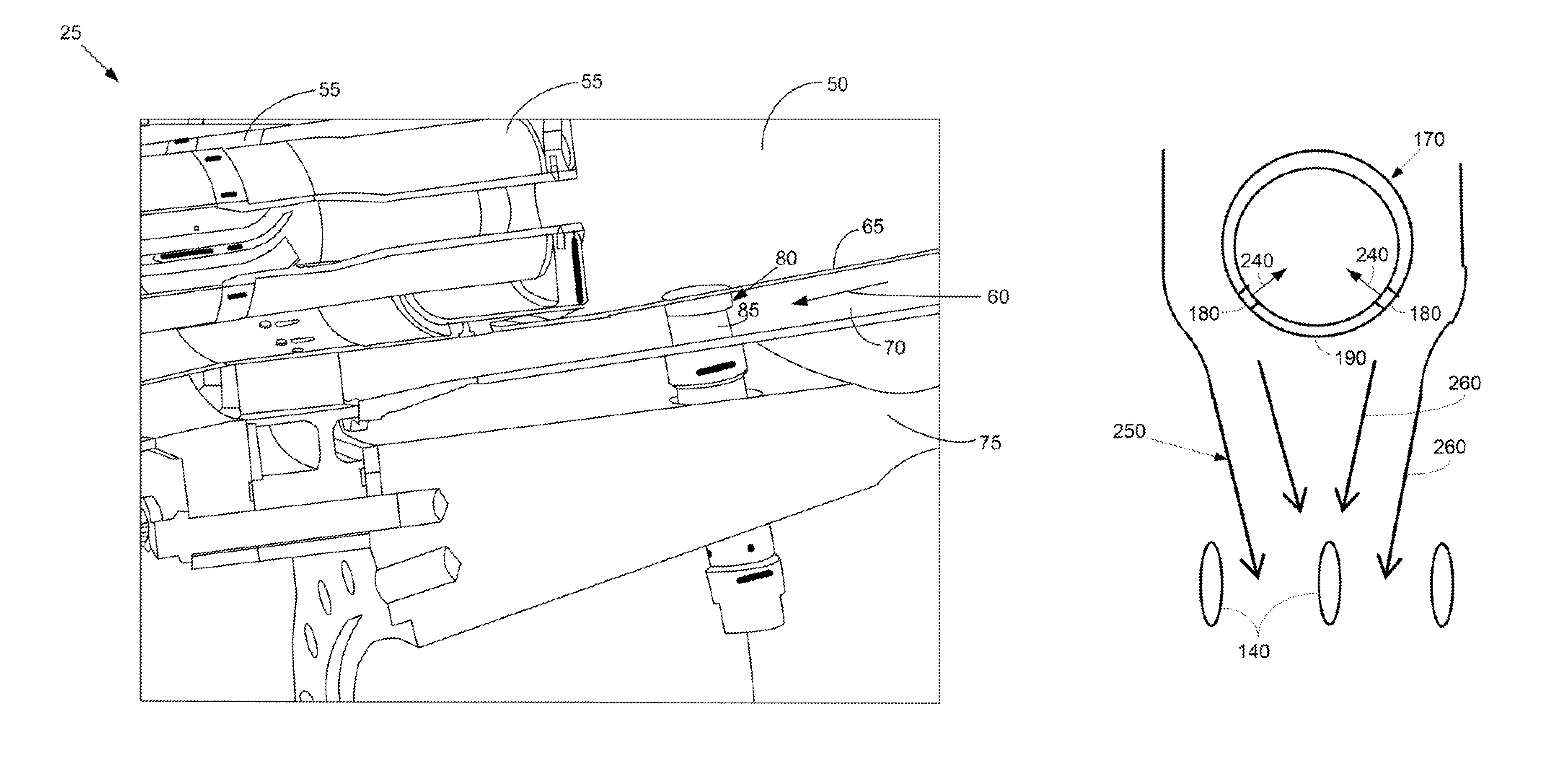
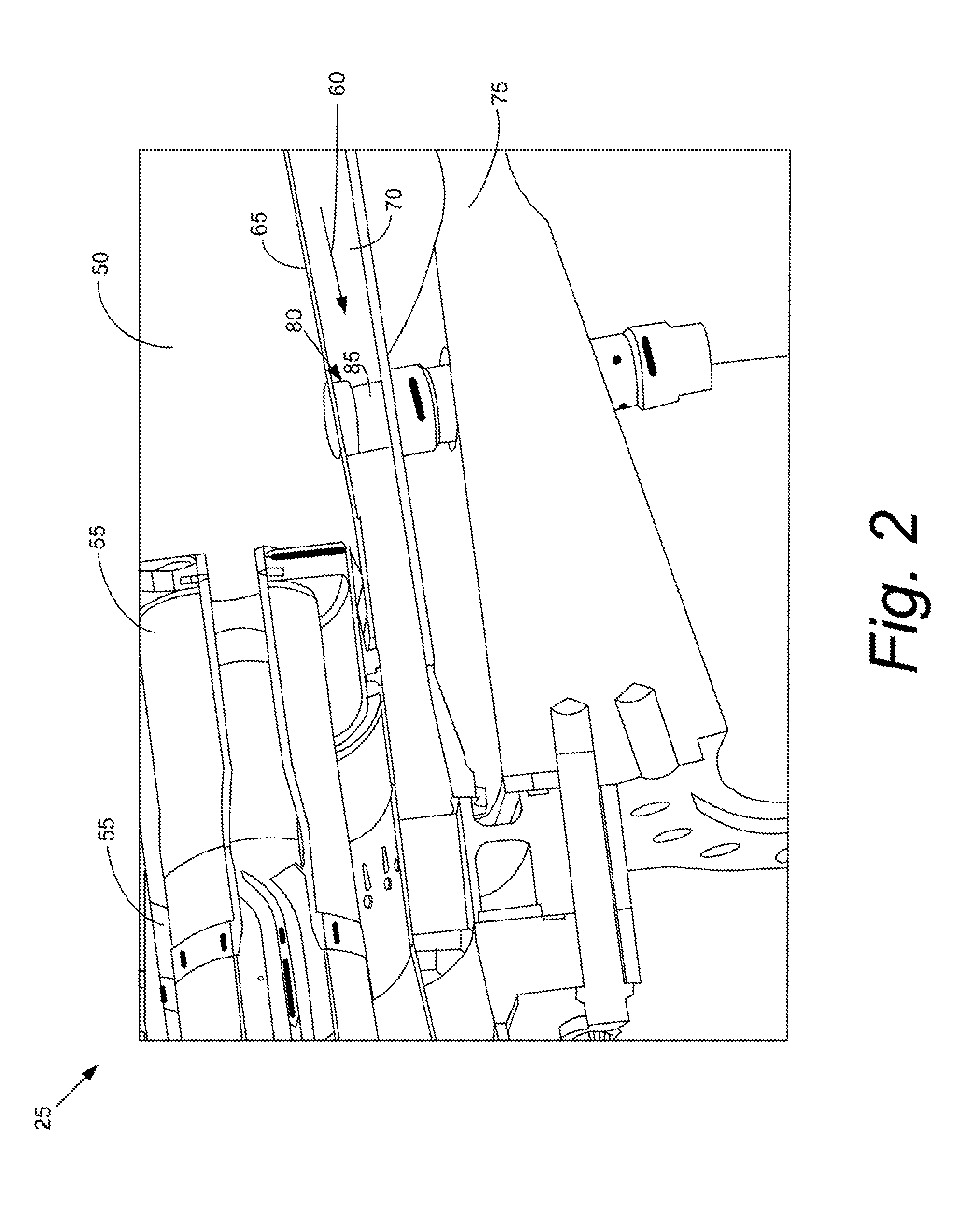
[0008]The present application and the resultant patent thus provide a combustor for mixing a flow of air and a flow of fuel. The combustor may include an air path for the flow of air, a number of fuel injectors positioned in the air path for the flow of fuel, and a crossfire tube positioned within the air path upstream of the fuel injectors. The crossfire tube may include a number of purge holes positioned on a downstream side thereof so as to reduce a wake in the flow of air caused by the crossfire tube in the air path.
[0009]The present application and the resultant patent further provide a method of operating a pre-nozzle fuel injection system. The method may include the steps of flowing air through an air path, flowing fuel through a number of fuel injectors, creating a wake in the flow of air upstream of the fuel injectors with a crossfire tube, flowing purge gas through a number of purge holes in the crossfire tube, creating an area of boundary layer suction about the crossfire tube, and eliminating or reducing the wake upstream of the fuel injectors by the area of boundary layer suction.

Problems solved by technology

Higher combustion stream temperatures, however, may result in the production of higher levels of nitrogen oxides (“NOx”) and other types of undesirable emissions.
Such premixing tends to reduce overall combustion temperatures and, hence, nitrogen oxide emissions and the like.
Premixing, however, may present several operational issues such as flame holding, flashback, auto-ignition, and the like.
These issues may be a particular concern with the use of highly reactive fuels.
Any type of fuel rich pocket thus may sustain a flame and cause damage to the combustor.
Other premixing issues may be due to irregularities in the fuel flows and the air flows.
For example, there are several flow obstructions that may disrupt the flow through an incoming pathway between a flow sleeve and a liner.
With a combustor having fuel injector vanes that inject fuel into the airflow upstream of the head-end, these flow disturbances may create flow recirculation zones on the trailing edge of the vanes.
As such, the crossfire tubes may cause a wake in the flow path that may envelop one or more of the premixing fuel injectors.
As described above, such a wake may cause recirculation zones and, hence, fuel holding and other types of flow disturbances.

Method used


Image

  • Combustor crossfire tube
  • Combustor crossfire tube
  • Combustor crossfire tube

Examples


Embodiment Construction

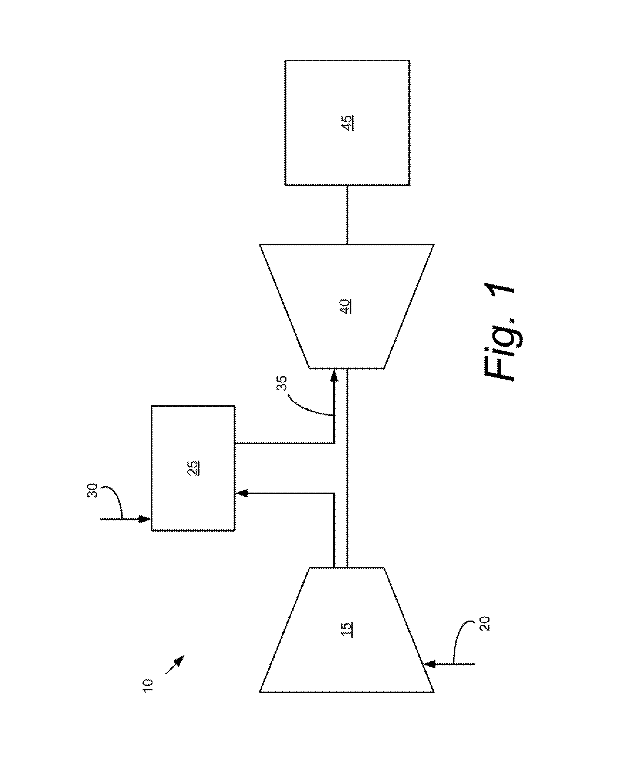
[0017]Referring now to the drawings, in which like numerals refer to like elements throughout the several views, FIG. 1 shows a schematic view of gas turbine engine 10 as may be used herein. The gas turbine engine 10 may include a compressor 15. The compressor 15 compresses an incoming flow of air 20. The compressor delivers the compressed flow of air 20 to a combustor 25. The combustor 25 mixes the compressed flow of air 20 with a compressed flow of fuel 30 and ignites the mixture to create a flow of combustion gases 35. Although only a single combustor 25 is shown, the gas turbine engine 10 may include any number of combustors 25. The flow of combustion gases 35 is in turn delivered to a turbine 40. The flow of combustion gases 35 drives the turbine 40 so as to produce mechanical work. The mechanical work produced in the turbine 40 drives the compressor 15 and an external load 45 such as an electrical generator and the like.

[0018]The gas turbine engine 10 may use natural gas, vari...


PUM


Abstract

The present application and the resultant patent provide a combustor for mixing a flow of air and a flow of fuel. The combustor may include an air path for the flow of air, a number of fuel injectors positioned in the air path for the flow of fuel, and a crossfire tube positioned within the air path upstream of the fuel injectors. The crossfire tube may include a number of purge holes positioned on a downstream side thereof to reduce a wake in the flow of air caused by the crossfire tube in the air path.

Description

TECHNICAL FIELD[0001]The present application relates generally to gas turbine engines and more particularly relates to gas turbine engine combustors with crossfire tubes having purge holes positioned therein to limit a wake or other types of flow disturbances downstream thereof.BACKGROUND OF THE INVENTION[0002]In a conventional gas turbine engine and the like, operational efficiency generally increases as the temperature of the combustion stream increases. Higher combustion stream temperatures, however, may result in the production of higher levels of nitrogen oxides (“NOx”) and other types of undesirable emissions. Such emissions may be subject to both federal and state regulation in the United States and also may be subject to similar regulations abroad. A balancing act thus exists between operating the gas turbine engine within an efficient temperature range while also ensuring that the output of nitrogen oxides and other types of regulated emissions remain below the mandated lev...

Claims


Application Information

Patent Timeline
Patent Type & Authority Patents(United States)
IPC IPC(8): F23R3/48F02C7/22
CPCF23R3/48F23R3/286
Inventor ANTONIONO, CAROLYN ASHLEYMELTON, PATRICK BENEDICT
Owner GENERAL ELECTRIC CO
Why Eureka
Try Eureka