Enhanced biometry using optical coherence tomography

a biometric and coherence tomography technology, applied in the field of enhanced biometrics using optical coherence tomography, can solve the problems of less reproducibility, less accuracy of ultrasonic measurements, and less precise ultrasonic measurements

Active Publication Date: 2014-11-25
OPTOVUE
View PDF30 Cites 20 Cited by
  • Summary
  • Abstract
  • Description
  • Claims
  • Application Information

AI Technical Summary

Problems solved by technology

However, the results from ultrasonic measurements may be less accurate and less reproducible than optical methods.
First, the ultrasonic wavelength is typically longer than the optical wavelength making the ultrasonic measurements less precise.
Second, if a contact ultrasonic probe is used, pressure applied to the cornea may distort the axial length measurement.
Third, an immersion ultrasonic probe can be uncomfortable for the patient.
Finally, it is difficult to accurately place the ultrasound probe on the desired measurement axis of the eye.
However, the ultrasonic measurement can often be performed even when there is a dense cataract, which renders measurement using optical methods difficult.
Current optical biometers only obtain measurements on a single axis of the eye and are therefore unable to create an image of the cornea or retina.
However, in unusual eyes or eyes that have undergone refractive surgery, the relationship between the anterior and posterior corneal surfaces is likely to be altered and the assumptions of the traditional IOL calculation formulas become invalid.

Method used


Image

  • Enhanced biometry using optical coherence tomography
  • Enhanced biometry using optical coherence tomography
  • Enhanced biometry using optical coherence tomography

Examples


Embodiment Construction

[0027]Various embodiments of the present invention are described below with reference to the accompanying drawings. It is understood that figures have been simplified for the purposes of explanation herein while leaving out elements which are conventional in the art.

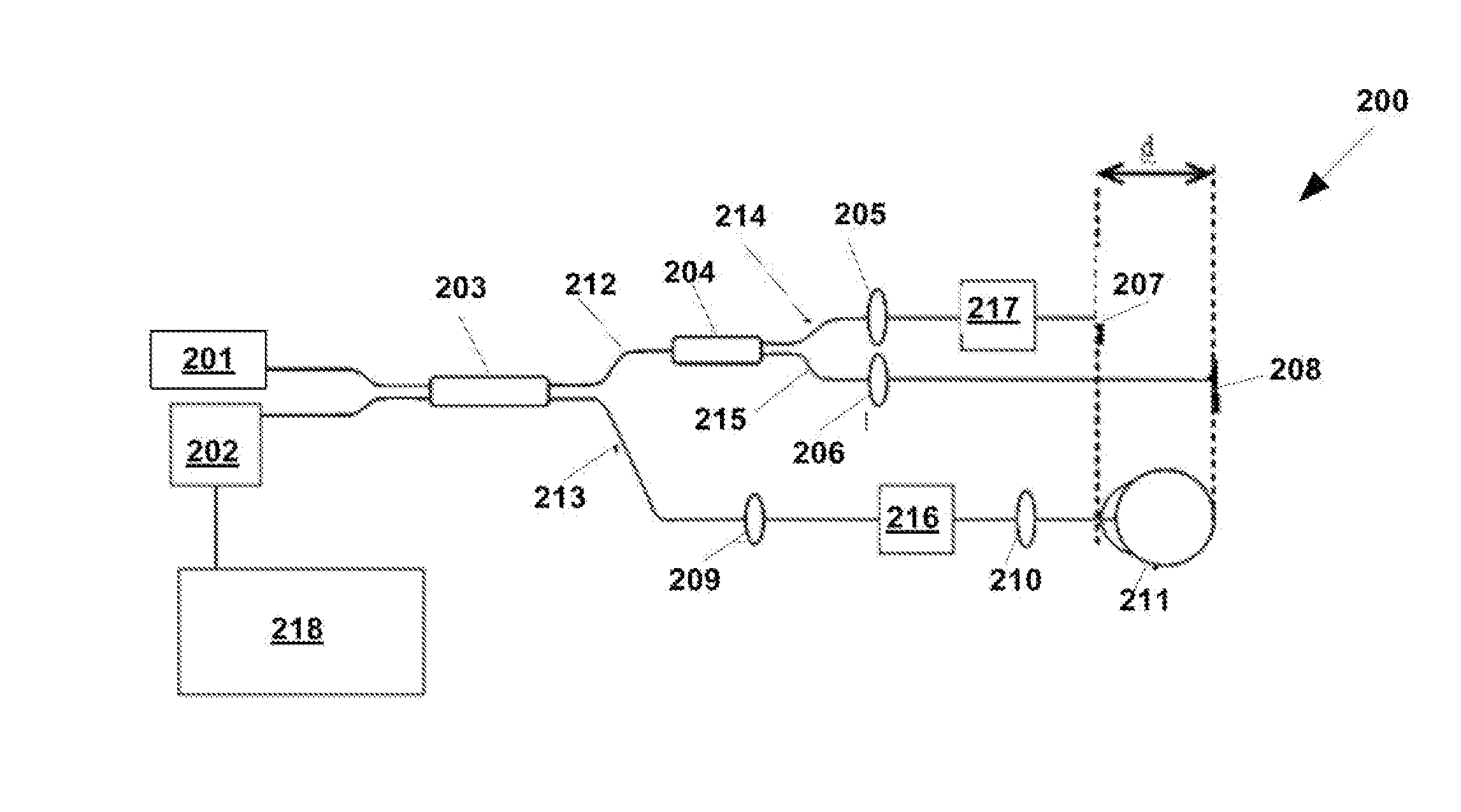
[0028]Optical methods of axial eye measurement described below can provide a high precision measurement because the wavelength of light is smaller than the ultrasonic wavelength. Measurements using optical methods can also be obtained without contact with the eye. In addition, the user may be able to manually align the optical measurement beam to the desired optical axis of the eye by monitoring the specular reflection of light from the cornea.

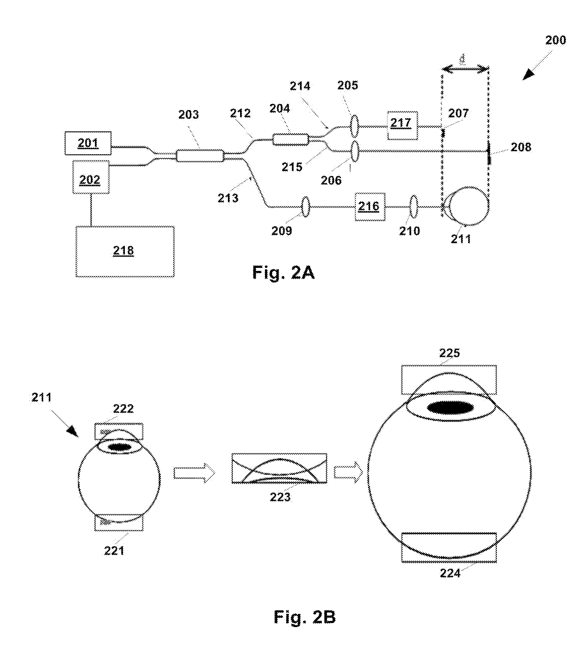
[0029]In some embodiments, the optical biometry can be improved by utilizing a plurality of measurements acquired at a plurality of transverse locations across the eye. In some embodiments, an apparatus that can couple an optical biometer to a beam scanning mechanism and a method u...


PUM


Abstract

An imaging method is disclosed. An imaging method according to some embodiments can include obtaining a plurality of measurements of an eye for at least one location by scanning optical radiation across the eye; determining a preferred measurement axis from the plurality of measurements; and processing the plurality of measurements to obtain information of the eye.

Description

RELATED APPLICATIONS[0001]This application claims priority to U.S. Provisional Application 61 / 608,047, filed on Mar. 7, 2012, which is herein incorporated by reference in its entirety.BACKGROUND[0002]1. Field of the Invention[0003]Embodiments of the present invention relate to a device for optical coherence tomography for determining geometric structures and optical biometry of the eye. In particular, embodiments of the present invention relate to a device for optical coherence tomography for determining the power of an intraocular lens implant and the condition of the retina.[0004]2. Description of Related Art[0005]Modern intraocular lens (IOL) calculation formulas rely on the measurement of several geometric parameters of the eye in order to calculate the power of an implanted intraocular lens after cataract surgery. Third-generation formulas such as the SRK / T (Retzlaff J A, Sanders D R, Kraff M C, “Development of the SRK / T intraocular lens implant power calculation formula” J Cat...

Claims


Application Information

Patent Timeline
Patent Type & Authority Patents(United States)
IPC IPC(8): A61B3/14A61B3/00
CPCA61B3/1025A61B3/1005A61B3/102A61B3/152
Inventor HEE, MICHAELWEI, JAYJANG, BENKO, TONY
Owner OPTOVUE
Why Eureka
Try Eureka