
Wing slot seal

a technology of slot sealing and wings, applied in the direction of wings, direction controllers, transportation and packaging, etc., can solve the problems of increasing weight and cost of missiles, internal components can also be exposed to induced contaminants, and internal components can be exposed to contaminated contaminants, so as to reduce the risk of bursting or dislodge, the effect of reducing the risk of bursting

Active Publication Date: 2014-11-25
BAE SYST INFORMATION & ELECTRONICS SYST INTEGRATION INC
View PDF22 Cites 7 Cited by
  • Summary
  • Abstract
  • Description
  • Claims
  • Application Information

AI Technical Summary

Benefits of technology

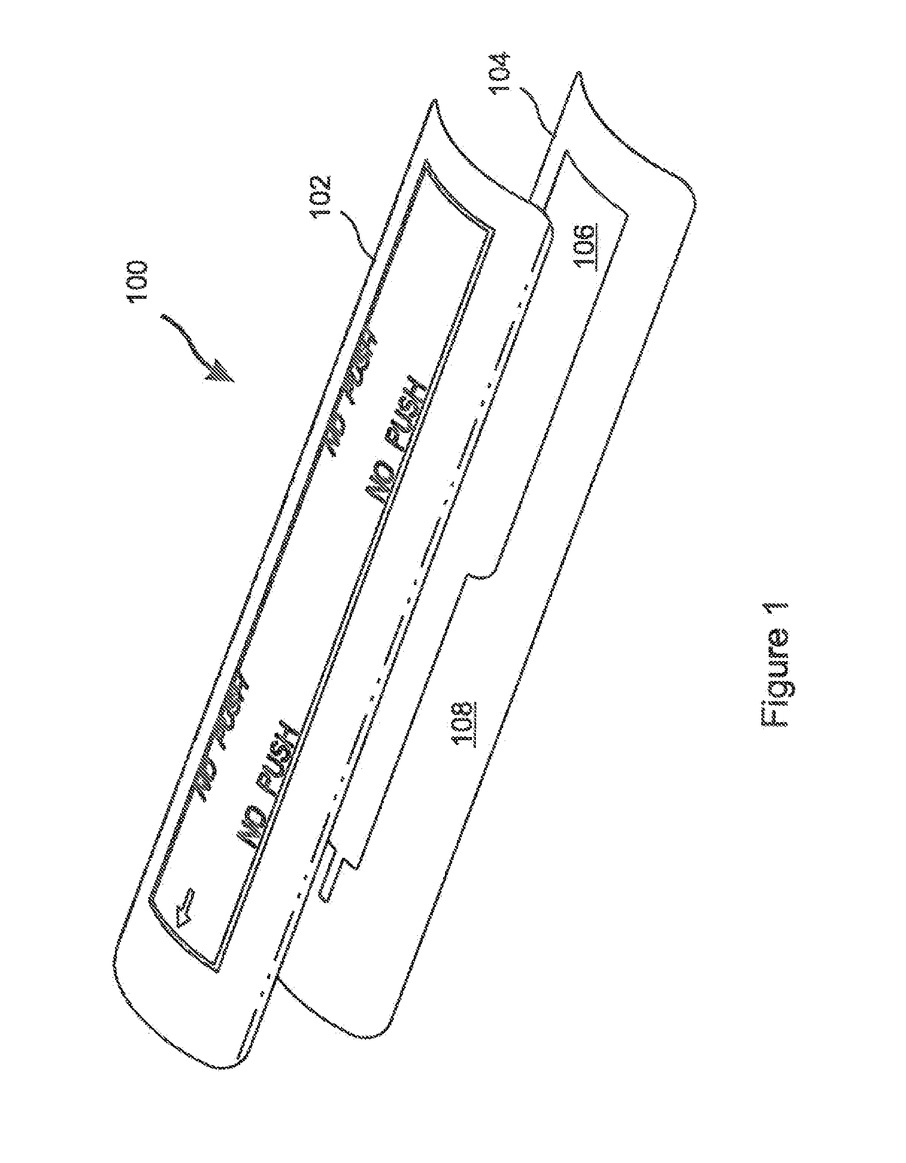
[0008]The present invention is a simple, low cost, lightweight wing slot seal which provides a frangible barrier against exposure of internal components of a rocket or missile to external contaminants, while enabling deployment of a wing stored within the rocket or missile simply by bursting of the wing through the frangible seal. The seal is strong enough to resist rupture or dislodgement from the exterior due to normal transport and handling of the missile, while at the same time presenting minimum resistance to penetration from the interior when the guidance wings are deployed by bursting through the seal. The invention itself includes no moving parts, and is therefore unaffected by exposure to contaminants. The simple design of the invention also provides no significant increase in the likelihood of weapon failure.
[0011]In embodiments, the flexible sheet is resilient or “springy,” so that once the wing is deployed, portions of the flexible sheet which lie against the deployed wing remain substantially flush against the wing, while portions of the flexible sheet which are not adjacent to the deployed wing tend to spring back into place and close the opening made in the frangible seal. The effect of the frangible seal on the aerodynamics of the rocket or missile is thereby minimized.
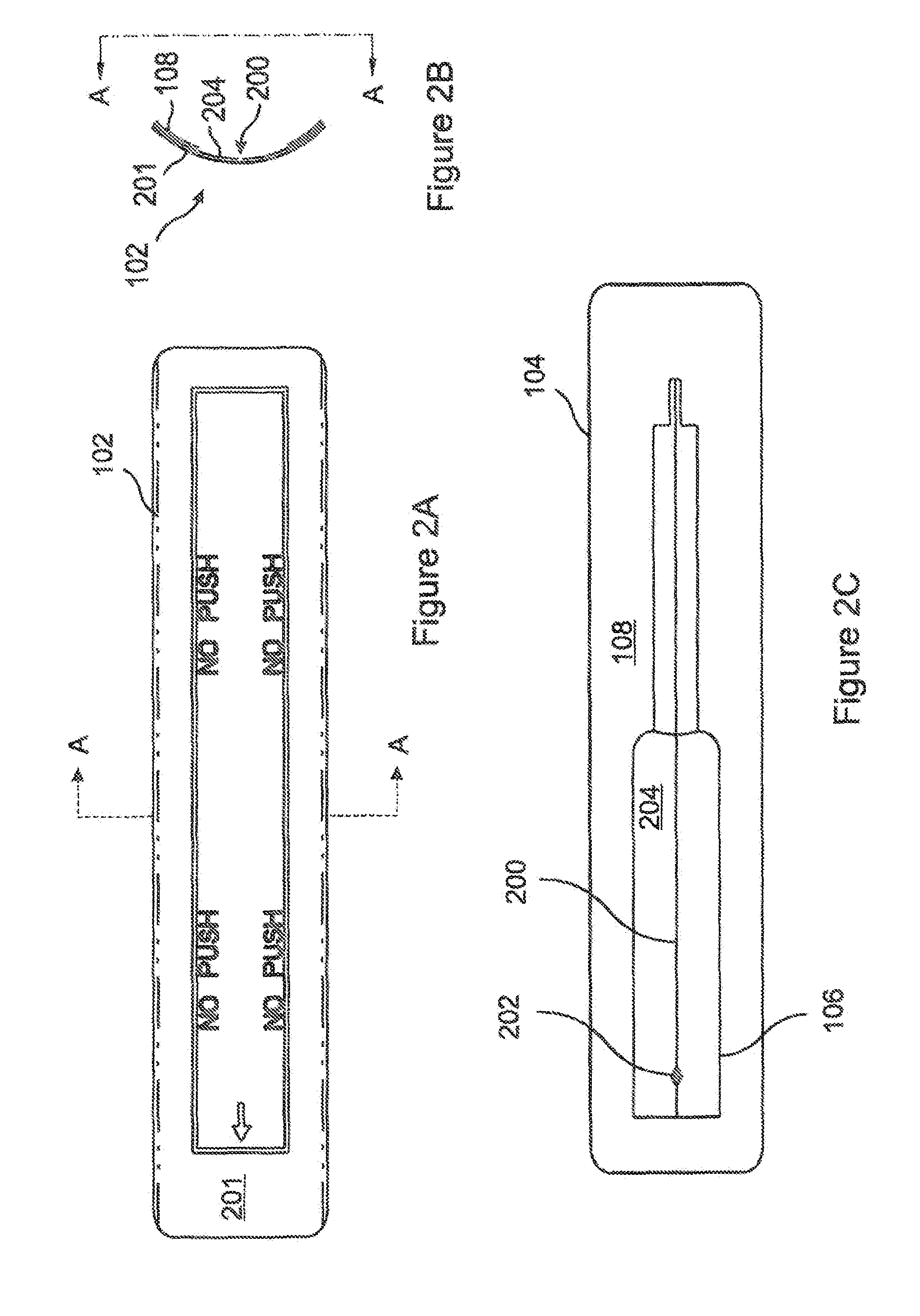
[0012]Embodiments of the invention include a puncture feature at a location where the wing first makes contact with the seal during wing deployment. The puncture feature includes a region where the inner layer is omitted and where at least one puncture initiator is attached to the inner surface of the outer layer, the puncture initiators being isolated from each other and from the inner layer. The puncture initiators are arranged so that impact with the leading edge of the wing during the initial stages of wing deployment will tend to drive the puncture initiators into the outer layer, causing the puncture initiators to pierce the outer layer and to provide perforations which will assist the wing in breaking through the outer layer.
[0014]The wing slot seal further includes a burst seam formed in the stiff layer of the barrier sheet, the burst seam being configured so as to allow a guidance wing to separate and pass through the burst seam during deployment of the guidance wing, the burst seam being configured to close and resist penetration when a force is applied to the barrier sheet from outside of the rocket or missile, and an adhesive layer at least applicable to an inner surface of the barrier sheet, the adhesive layer being configured for adhering the barrier sheet to the region of fuselage surrounding the wing slot, the adhesive layer providing an adhesive strength which is sufficient to maintain the barrier sheet in position over the wing slot while the guidance wing breaks through the barrier sheet during deployment of the guidance wing.
[0019]In certain embodiments the wing slot seal is able to inhibit penetration of moisture through the wing slot. And some embodiments further include an alignment feature suitable for alignment with a compatible alignment feature provided on the fuselage of the rocket or missile, the alignment feature thereby facilitating attachment of the wing slot seal to the fuselage at a desired location and with a desired alignment.

Problems solved by technology

While foldable wing designs provide the advantages of compact storage and reduced launcher size, the slots in the fuselage required for deployment of the wings tend to create a hazard that internal components of the weapon will be exposed to contaminants.
The internal components can also be exposed to induced contaminants, such as debris from an adjacent rocket launch, and contaminants resulting from handling of the missile.
However, such mechanisms add weight and cost to the missile, take up space which may be needed for other components, and tend to be complex and prone to failure.

Method used


Image

  • Wing slot seal
  • Wing slot seal
  • Wing slot seal

Examples


Embodiment Construction

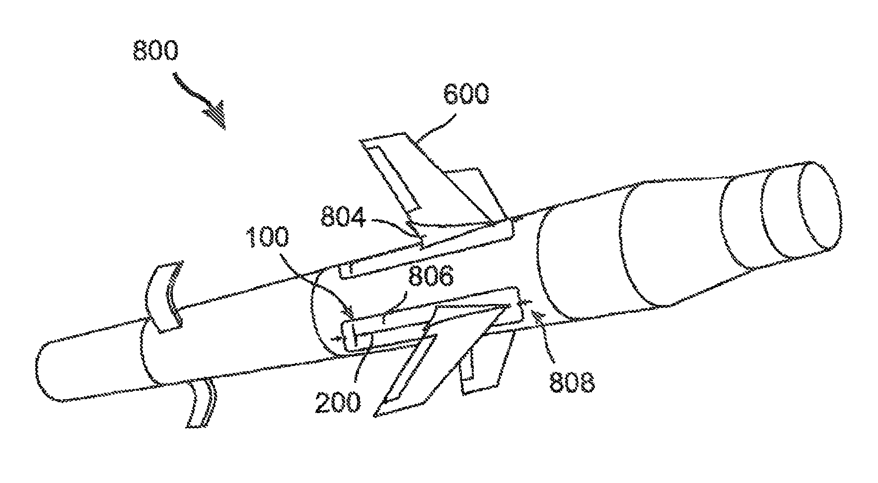
[0035]With reference to FIG. 1, the present invention is a simple, low cost, lightweight wing slot seal 100 which provides a frangible barrier against exposure of internal components of a rocket or missile (800 in FIG. 8) to external contaminants, while enabling deployment of a wing (600) stored within the rocket or missile (800) simply by bursting of the wing 600 through the frangible seal 100. The seal 100 is strong enough to resist rupture or dislodgement from the exterior of the rocket or missile 800 due to normal transport and handling of the rocket or missile 800, while at the same time presenting minimum resistance to penetration from the interior when the guidance wings 600 are deployed by bursting through the seal 100. The invention itself includes no moving parts, and is therefore unaffected by exposure to contaminants. The simple design of the invention also provides no significant increase in the likelihood of weapon failure.

[0036]The invention includes a thin, flexible ...


PUM


Abstract

A low cost, lightweight frangible wing slot seal can be applied to a guidance wing slot of a folding fin aerial rocket or missile, providing a barrier against exposure of internal missile components to external contaminants, while allowing unhindered deployment of missile guidance wings simply by bursting through the seals. The simple design is nearly foolproof, and has no impact the likelihood of weapon failure. The seal is a flexible sheet which is sufficiently thin so as not to exceed the required volume envelope of the missile. The sheet includes a burst seam, which is breached when impacted by the leading edge of a deploying wing. No additional wing deployment force is required, and after deployment the seal has minimal impact on the aerodynamic performance of the wing.

Description

RELATED APPLICATIONS[0001]This application claims the benefit of U.S. Provisional Application No. 61 / 321,816, filed Apr. 7, 2010, herein incorporated by reference in its entirety for all purposes.STATEMENT OF GOVERNMENT INTEREST[0002]The invention was made with United States Government support under Contract No. W31P4Q-06-C-0330 awarded by the Navy. The United States Government has certain rights in this invention.FIELD OF THE INVENTION[0003]The invention relates to ballistic weaponry, and more particularly to folding fin aerial rockets and missiles.BACKGROUND OF THE INVENTION[0004]Aerial rockets and missiles which include guidance wings have been in use at least since the late 1940's, with the FFAR (Folding Fin Aerial Rocket) being used in the Korean and Vietnam conflicts, and the more recent Hydra 70 family of WAFAR (Wrap-Around Fin Aerial Rocket) and the Advanced Precision Kill Weapon. System (APKWS) laser guided missile. The guidance wings for these weapons are typically folded ...

Claims


Application Information

Patent Timeline
Patent Type & Authority Patents(United States)
IPC IPC(8): F42B10/14B64D45/00F42B10/00
CPCF42B10/14F42B39/00
Inventor BARRY, WILLIAM D.WINKLER, ROBERTFRANZINI, JOHN R.CLEVELAND, KENNETH D.BUTLAND, ADAM
Owner BAE SYST INFORMATION & ELECTRONICS SYST INTEGRATION INC
Learn More