Nitride semiconductor light emitting device
a technology of light-emitting devices and semiconductors, which is applied in the direction of semiconductor devices, basic electric elements, electrical equipment, etc., can solve the problems of reducing the internal quantum efficiency of the light-emitting layer, and achieve the effect of reducing color non-uniformity
- Summary
- Abstract
- Description
- Claims
- Application Information
AI Technical Summary
Benefits of technology
Problems solved by technology
Method used
Image
Examples
embodiment 1
[0146]Hereinafter, a semiconductor light-emitting device according to Embodiment 1 of the present disclosure will be described with reference to FIGS. 3A and 3B.
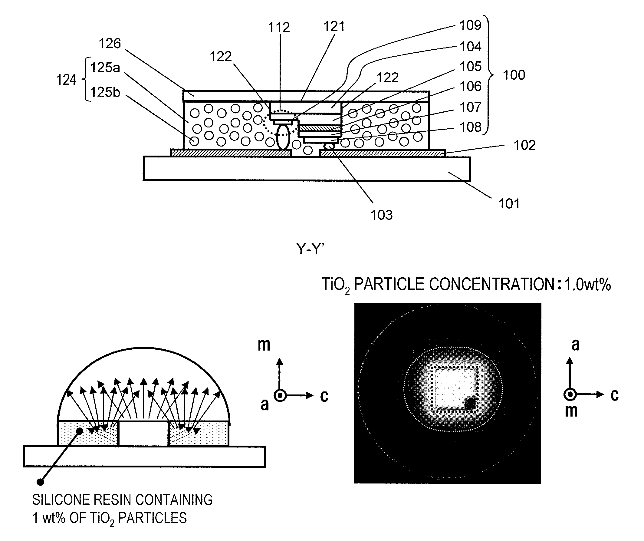
[0147]As shown in FIGS. 3A and 3B, a semiconductor light-emitting device in this embodiment includes a mounting substrate 101, a nitride semiconductor light-emitting chip 100 mounted on the mounting substrate 101, a first light-transmissive member 124 located to the side of the nitride semiconductor light-emitting chip 100, and a second light-transmissive member 126 located in an area above the nitride semiconductor light-emitting chip 100 (“above” refers to a direction opposite to the direction from the nitride semiconductor light-emitting chip 100 toward the mounting substrate 101).
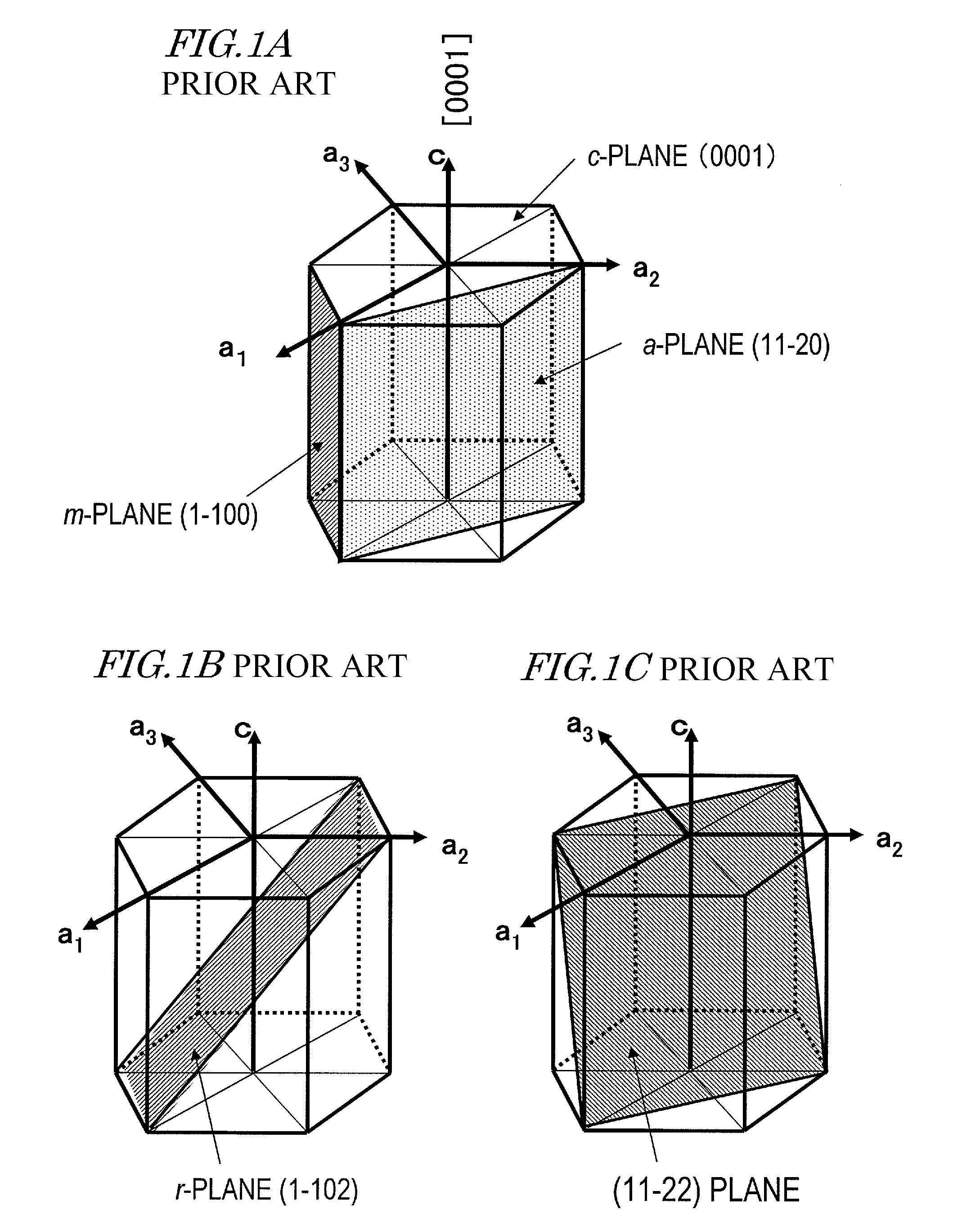
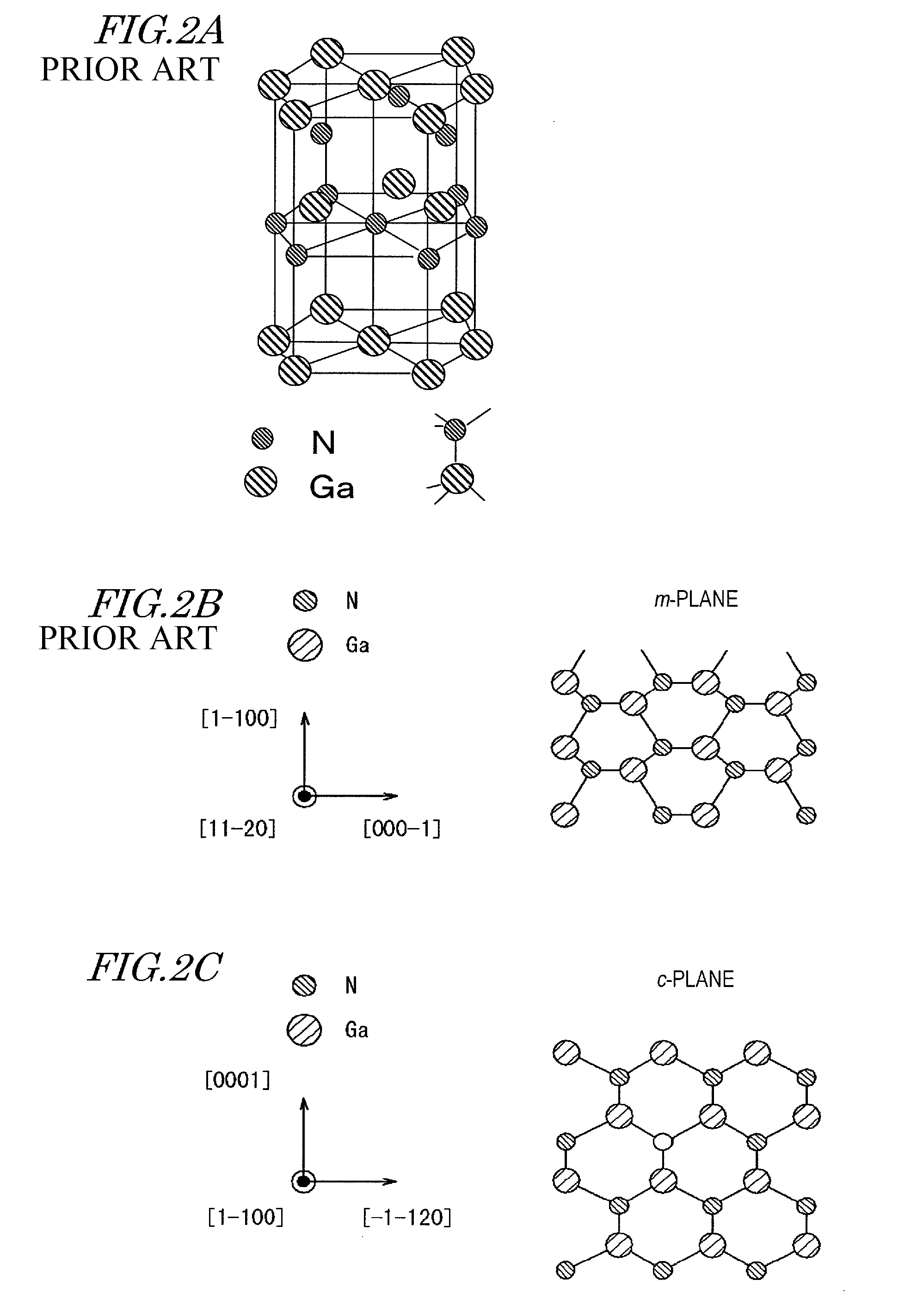
[0148]As shown in FIG. 3B, the nitride semiconductor light-emitting chip 100 includes a substrate 104 including a GaN layer having the m-plane as a main plane (and also a growth plane) (hereinafter, referred to as an “m-plane GaN layer”), an n-t...
embodiment 2
[0201]Hereinafter, a semiconductor light-emitting device according to Embodiment 2 according to the present disclosure will be described with reference to FIGS. 14A through 14F. In FIG. 14, identical elements to those in FIG. 3 will bear identical reference signs thereto and descriptions thereof will be omitted. This will be also applied to the following embodiments. Herein, differences of Embodiment 2 from Embodiment 1 will be described.
[0202]As shown in FIGS. 14A and 14B, in Embodiment 2, unlike in Embodiment 1, the first light extraction plane 121 has a plurality of projection and recess portions 104a having a plurality of projection and recess or texture. In the example of FIG. 14B, each projection portion of the projection and recess portions 104a has a generally semi-spherical cross-section in a direction perpendicular to the substrate surface. The projection and recess portions 104a at the rear surface of the substrate 104 can be produced by thinning the substrate 104, formin...
embodiment 3
[0210]Hereinafter, Embodiment 3 according to the present disclosure will be described with reference to FIGS. 15A and 15B.
[0211]FIGS. 15A and 15B are respectively a plan view and a cross-sectional view of a semiconductor light-emitting device in this embodiment. The semiconductor light-emitting device in this embodiment includes a semiconductor light-emitting chip 100, a wavelength converting member 112, and a first light-transmissive member 124. The semiconductor light-emitting device may further include a second light-transmissive member 126. As shown in FIG. 15B, the semiconductor light-emitting chip 100 has a semiconductor stacking structure formed of nitride semiconductors. The semiconductor stacking structure includes a substrate 104 having a GaN layer having the m-plane as a main plane (and also a growth plane) (hereinafter, such a GaN layer will be referred to as an m-plane GaN layer) on at least a surface thereof, an n-type nitride semiconductor layer 105 formed on the main...
PUM
 Abstract
Description
Claims
Application Information
 - R&D
- Intellectual Property
- Life Sciences
- Materials
- Tech Scout
- Unparalleled Data Quality
- Higher Quality Content
- 60% Fewer Hallucinations
Browse by: Latest US Patents, China's latest patents, Technical Efficacy Thesaurus, Application Domain, Technology Topic, Popular Technical Reports.
© 2025 PatSnap. All rights reserved.Legal|Privacy policy|Modern Slavery Act Transparency Statement|Sitemap|About US| Contact US: help@patsnap.com


