Ultrasonic vibration device

a technology of ultrasonic vibration and vibration device, which is applied in the direction of mechanical vibration separation, generator/motor, instruments, etc., can solve the problems of reducing the reverberation, difficulty in sufficiently suppressing the reverberation to obtain the characteristics required, and reducing the rigidity of the reverb. , to achieve the effect of suppressing the propagation of the vibration, increasing the rigidity, and reducing the rigidity

Active Publication Date: 2014-11-25
MURATA MFG CO LTD
View PDF22 Cites 2 Cited by
  • Summary
  • Abstract
  • Description
  • Claims
  • Application Information

AI Technical Summary

Benefits of technology

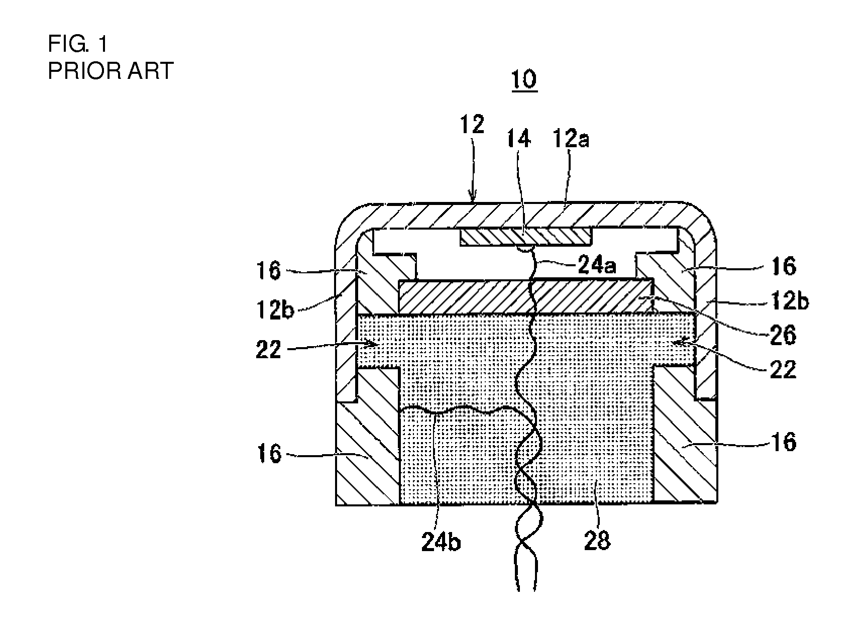
[0009]In the configuration of Patent Document 1, a side portion of the case is thick on the short-axis sides and thin on the long-axis sides of the substantially elliptical shape. Therefore, vibration generated by bending vibration of the piezoelectric element is propagated from the bottom surface of the case to the thin sides of a side wall portion of the case. This propagated vibration is damped by the elastic damping member or the like, and thereby the reverberation time is reduced. To obtain characteristics required for practical use by using this structure, however, it is required to damp the vibration per se occurring in the bottom surface of the case, i.e., an acoustic wave radiating surface.
[0012]In view of the above, an object of the present invention is to provide an ultrasonic vibration device intended to achieve high sensitivity, low reverberation, and low cost.
[0018]According to the present invention, the vibration suppression area and the reinforcing member reinforcing this are provided near the bottom surface of the case. Therefore, a portion of the bottom surface of the case corresponding to the vibration suppression area and the side portion of the case are increased in rigidity, and it is possible to more suppress the propagation of the vibration of the bottom surface of the case to the side portion of the case, and to form a vibration surface which transmits and receives necessary ultrasonic waves.
[0019]Further, with the above-described configuration, the entire circumference of the side portion of the case is reduced in thickness to reduce the rigidity thereof, and the interior of the case is filled with the filling member. Thereby, it is possible to increase the area of direct contact between the filling member and the case, and the vibration of the side portion of the case is more subject to damping. Therefore, the damping of the bottom portion of the case is not required, unlike the related art structure. Accordingly, it is possible to obtain reverberation performance without degrading acoustic performance, as compared with the related art.
[0020]Further, it is possible to reduce the difference in thickness of the entire case. Accordingly, it is possible to select a highly productive manufacturing method, such as forging, and to reduce the processing cost.

Problems solved by technology

If a member for damping the vibration (a filling member or the like, for example) is provided near the bottom surface of the case, however, the reverberation is reduced, but at the same time there arises an issue of degradation in sensitivity.
However, it has been found difficult to sufficiently suppress the reverberation to obtain characteristics required for practical use, even if the damping member is brought into direct contact with the side surface portion of the cap body through the through-holes of the inner frame.
Further, it is difficult, in terms of manufacturing method, to partially provide the inner frame with through-holes and completely cover the through-holes with a filling member.

Method used


Image

  • Ultrasonic vibration device
  • Ultrasonic vibration device
  • Ultrasonic vibration device

Examples


first embodiment

[0029

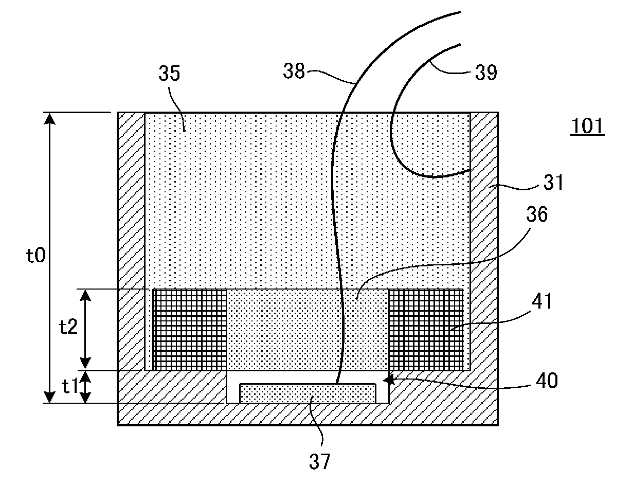
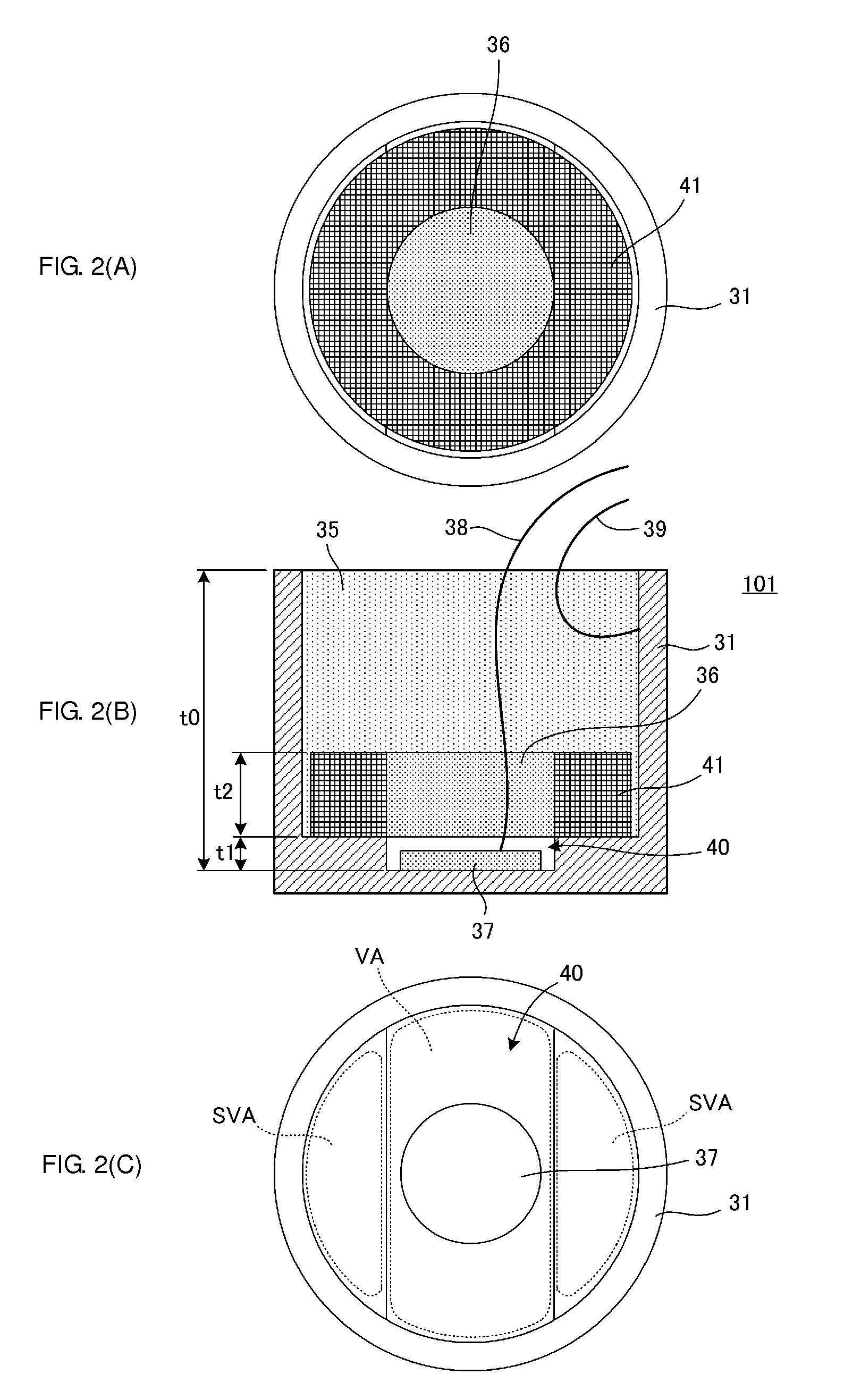
[0030]FIG. 2(A) is a plan view of an ultrasonic vibration device 101 according to a first embodiment before being filled with a filling member 35, as viewed from the side of an opening surface of a case 31. FIG. 2(B) is a cross-sectional view of the ultrasonic vibration device 101, and FIG. 2(C) is a plan view of the case 31 as viewed from the side of the opening surface thereof.

[0031]As illustrated in FIG. 2(B) and FIG. 2(C), the case 31 is a cylindrical case with a bottom. An inner bottom surface of the case 31 is formed with a substantially oblong recess 40 having a long axis and a short axis. A piezoelectric element 37 is bonded to the center of this recess 40 (also the center of the inner bottom surface of the case 31). The substantially oblong recess 40 in the inner bottom surface of the case 31 mainly forms a vibration area VA. Further, vibration suppression areas SVA thicker than the vibration area are disposed on the opposite sides of the vibration area VA in the inner...

second embodiment

[0065

[0066]FIG. 7(A) is a plan view of an ultrasonic vibration device 102 according to a second embodiment before being filled with a filling member 35, as viewed from the side of an opening surface of a case 31. FIG. 7(B) is a cross-sectional view of the ultrasonic vibration device 102, and FIG. 7(C) is a plan view of the case 31 as viewed from the opening surface thereof.

[0067]The structure of the case 31 is the same as the one illustrated in FIGS. 2(A) to 2(C) in the first embodiment. As illustrated in FIG. 7(C), an inner bottom surface of the case 31 is formed with a substantially oblong recess 40 having a long axis and a short axis. A piezoelectric element 37 is bonded to the center of this recess 40. The substantially oblong recess 40 in the inner bottom surface of the case 31 mainly forms a vibration area VA. Further, vibration suppression areas SVA thicker than the vibration area are disposed on the opposite sides of the vibration area VA in the inner bottom surface of the c...

third embodiment

[0073

[0074]FIG. 8(A), FIG. 8(B), and FIG. 8(C) are plan views of three types of reinforcing members used in an ultrasonic vibration device according to a third embodiment.

[0075]Although the ring-shaped reinforcing member 41 is provided in the first and second embodiments, it suffices if the reinforcing member has a structure reinforcing the two vibration suppression areas SVA. For example, the reinforcing member may be divided into two parts, as in reinforcing members 51 and 52 illustrated in FIG. 8(A). In this case, the reinforcing member serving as a weight on the vibration suppression areas SVA extends across the two vibration suppression areas SVA. Thereby, the reinforcing member is not displaced together with the vibration suppression areas SVA, and it is possible to enhance the effect of the reinforcing member. Further, the reinforcing member may be integrated into a disc shape, as in a reinforcing member 52 illustrated in FIG. 8(B). Further, the reinforcing member may have a ...


PUM


Abstract

In an inner bottom surface of a case, a substantially oblong recess having a long axis and a short axis forms a vibration area. A piezoelectric element is bonded to the center of the recess. On the opposite sides of the vibration area, vibration suppression areas thicker than the vibration area are disposed. A side portion of the case is formed to be thin over the entire circumference thereof. A reinforcing member higher in rigidity than the case is bonded to upper portions of the vibration suppression areas. The reinforcing member has a bottom surface substantially equal to the shape of the vibration suppression areas, and has a predetermined height. A gap between the reinforcing member and an inner side surface of the case is also filled with a filling member.

Description

CROSS REFERENCE TO RELATED APPLICATIONS[0001]The present application is a continuation of International application No. PCT / JP2011 / 051278, filed Jan. 25, 2011, which claims priority to Japanese Patent Application No. 2010-012691, filed Jan. 25, 2010, and Japanese Patent Application No. 2010-213163, filed Sep. 24, 2010, the entire contents of each of which are incorporated herein by reference.FIELD OF THE INVENTION[0002]The present invention relates to an ultrasonic vibration device used in an ultrasonic sensor or the like which detects an object by transmitting and receiving ultrasonic waves.BACKGROUND OF THE INVENTION[0003]An ultrasonic sensor which measures the distance to a target object by using ultrasonic waves is requested to have sharp directivity. To improve the directivity of the ultrasonic sensor, the vibration mode of a vibration surface has been devised in the past.[0004]For example, ultrasonic vibration devices each serving as an on-vehicle ultrasonic sensor for a back ...

Claims


Application Information

Patent Timeline
Patent Type & Authority Patents(United States)
IPC IPC(8): G10K9/122H01L41/053B06B1/06G10K9/22
CPCB06B1/0685G10K9/22G10K9/122G01S7/521H04R17/00
Inventor MATSUO, KENJI
Owner MURATA MFG CO LTD
Why Eureka
Try Eureka