Device for ascertaining a fill level of a medium

a technology for ascertaining the fill level and medium, which is applied in the direction of liquid/fluent solid measurement, instruments, machines/engines, etc., can solve the problems of insufficient accuracy, relatively imprecise fill level measurement, and the medium in the measuring chamber accordingly rises, so as to achieve the effect of deflecting or baffle surface and improving the reliability of the devi

Active Publication Date: 2014-12-02
HELLA KG HUECK & CO
View PDF13 Cites 3 Cited by
  • Summary
  • Abstract
  • Description
  • Claims
  • Application Information

AI Technical Summary

Benefits of technology

[0013]It is also in the scope of the invention that the flow damper is a planar element, which has at least one deflection surface having an overflow edge for the medium. The planar element, which is oriented perpendicular to the surface normal line in the antechamber, extends in particular over the entire width of a subsection and over a predetermined height of the antechamber. The medium flowing into a respective antechamber is therefore effectively deflected on the deflection or baffle surface. The planar element preferably has only a single overflow edge. In addition, the inlet area of the antechamber may advantageously be changed or adapted accordingly in its size using such a contour part, so that the origination of flows in the inlet area of an antechamber, which generate excess pressures or partial vacuums, is advantageously prevented.
[0014]The planar element has a plurality of damping bodies protruding thereon on at least one of its deflection surfaces, with the aid of which the origination of flows is additionally counteracted in the inlet area of the antechamber. With the aid of the damping bodies, in particular on both deflection surfaces of the planar element, the reliability of the device is further advantageously improved during the ascertainment of a fill level in a collection container. The origination of a Schlichting flow is counteracted best in that the damping bodies, which protrude into a possible flow, swirl the flow, so that it becomes diffuse. Therefore, no pressure buildup or pressure drop occurs at the inlet opening of the device or a respective antechamber, whereby an excessive increase or drop of the liquid level in the measuring chamber is always reliably prevented.

Problems solved by technology

Especially in the case of measurements of the fill level in the oil catch container of an engine, inaccuracies can occur during the measurement, since the continuous circulation of the medium typically results in foaming of the oil, gas bubbles forming in the medium.
The level of the medium in the measuring chamber accordingly rises or falls excessively, which results in a relatively imprecise fill level measurement.

Method used


Image

  • Device for ascertaining a fill level of a medium
  • Device for ascertaining a fill level of a medium
  • Device for ascertaining a fill level of a medium

Examples


Embodiment Construction

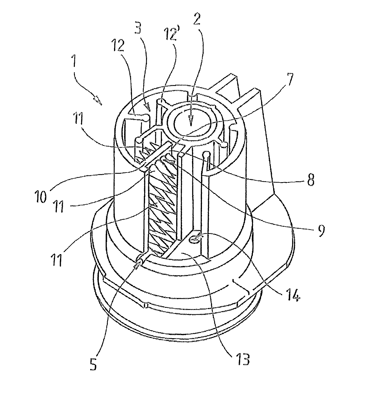
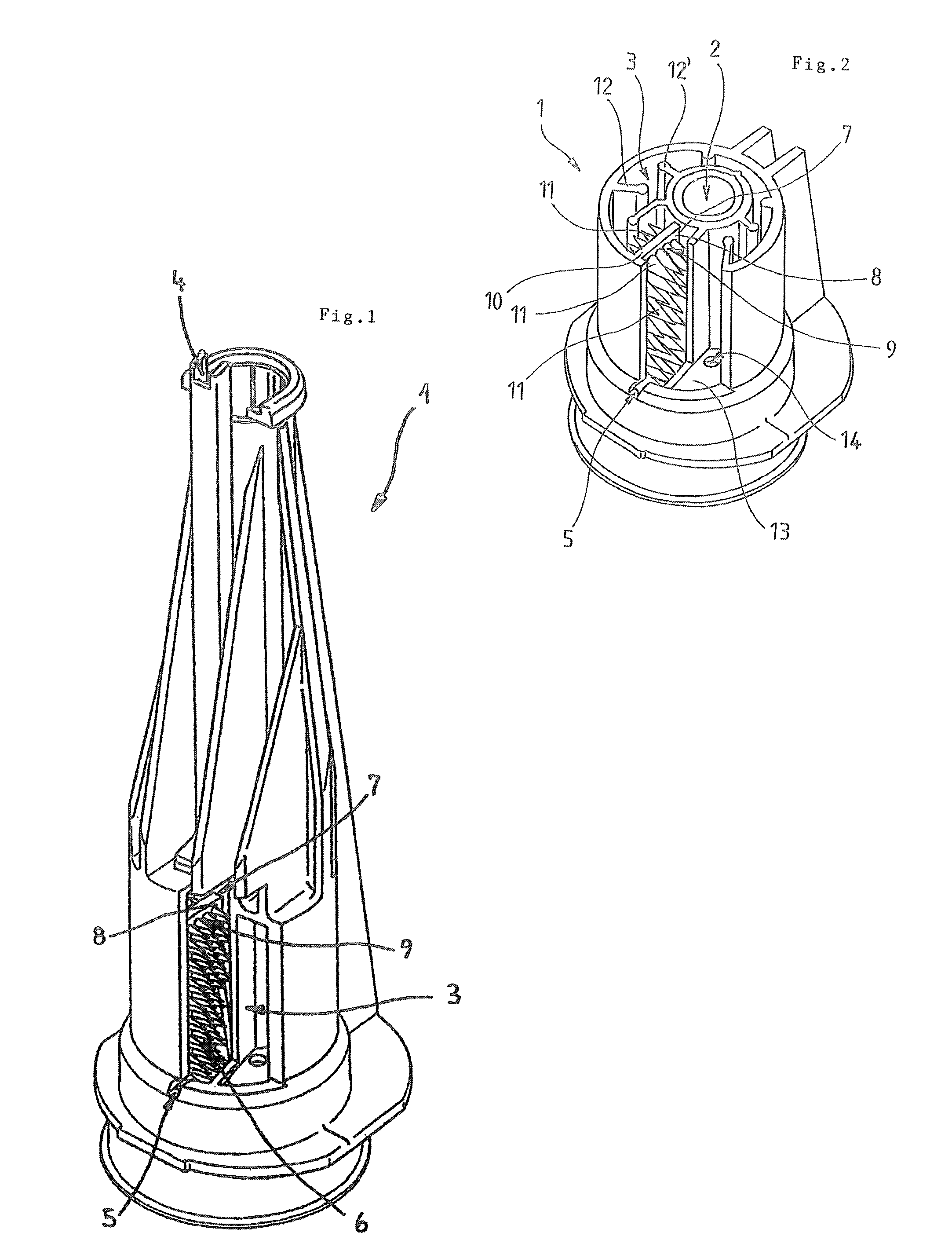
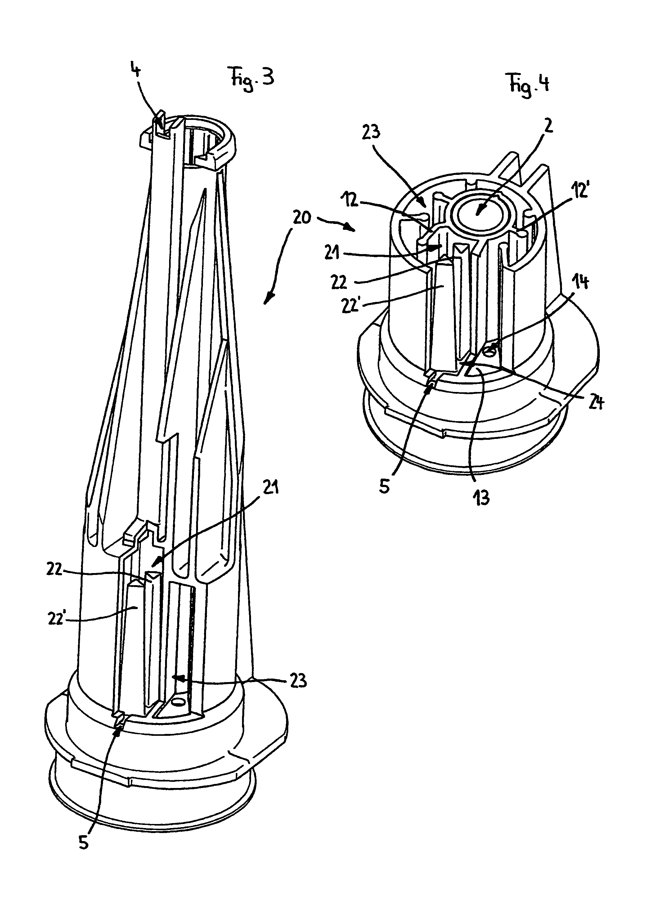
[0023]A device for ascertaining a fill level of a medium in a container (not shown) is identified by 1, which has at least one measuring chamber 2 (FIG. 2), in which the level of the medium is ascertained with the aid of an ultrasonic sensor (not shown). At least one first antechamber 3, in which in particular the medium flowing from the container into the antechamber 3 is to calm down and possible gas bubbles located in the liquid medium are to be separated, is connected upstream from the measuring chamber 2. For this purpose, the device has at least one deaeration unit 4. Furthermore, a flow damper 7 is provided immediately behind the inlet opening 5 of the first antechamber 3 in its inlet area 6. Possible flows oriented in opposite directions, which form arbitrarily immediately behind the inlet opening in specific operating states of an engine, are to be prevented from originating with the aid of the flow damper 7.

[0024]As FIG. 2 illustrates, the flow damper 7 is implemented in p...


PUM


Abstract

In the case of a device for ascertaining a fill level of a medium inside a collection container, having at least one measuring chamber, in which an ultrasonic sensor is arranged, connected to conduct media to the collection chamber, and having at least one antechamber connected upstream from the measuring chamber, which has at least one inlet opening for the medium from the collection chamber, at least one flow damper for the medium, according to the invention, is arranged in at least one subarea of the antechamber. Thereby multiple antechambers, which are connected in series one behind another to conduct media, are connected upstream from the measuring chamber.

Description

[0001]Under 35 U.S.C §119, Applicants claim priority to the earlier filed German Patent Application, Serial No. 102011 008 585.8 filed on Jan. 14, 2011.BACKGROUND OF THE INVENTION[0002]The invention relates to a device for ascertaining a fill level of a medium, in particular inside a collection container, having at least one measuring chamber, in which an ultrasonic sensor is arranged, connected to conduct media to the collection container, and having at least one antechamber connected upstream from the measuring chamber, which has at least one inlet opening for the medium from the collection container.BRIEF SUMMARY OF THE INVENTION[0003]Devices of the above-mentioned species are used in particular in collection containers for liquid media, for example, in an oil catch container of an engine, in particular to be able to ascertain the fill level of the medium, such as oil or fuel, within the container. The devices typically have an ultrasonic sensor for this purpose, which is frequen...

Claims


Application Information

Patent Timeline
Patent Type & Authority Patents(United States)
IPC IPC(8): G01F23/296
CPCG01F23/2962G01F23/296
Inventor NIEMANN, THOMASPALLOKS, JÜRGENKÜCK, THOMASHESSENKÄMPER, DAVIDZOYKE, INGOCLAASSEN, HERBERT
Owner HELLA KG HUECK & CO
Why Eureka
Try Eureka