Laser-arc hybrid welding head

a hybrid welding and laser arc technology, applied in laser beam welding apparatus, electrode supporting devices, manufacturing tools, etc., can solve the problems of requiring a strict working accuracy for the groove, affecting the welding effect, and the end of the head cannot be brought closer to the base material than required, so as to achieve the effect of efficiently deflecting laser ligh

Inactive Publication Date: 2012-03-20
HONDA MOTOR CO LTD +1
View PDF3 Cites 2 Cited by
  • Summary
  • Abstract
  • Description
  • Claims
  • Application Information

AI Technical Summary

Benefits of technology

[0018]The laser-arc hybrid welding head according to the present invention can deflect laser light efficiently, thereby performing welding, without contacting surrounding members, even when used within a narrow space.

Problems solved by technology

With the aforementioned laser welding process, however, since laser light is focused, a groove tolerance is low, thus requiring a strict working accuracy for the groove.
With the above-mentioned arc welding process, if welding is performed at a high speed, the arc may be unstable, or the large amount of heat input may result in a great thermal strain.
Thus, the leading end of the head cannot be brought closer to the base material than required.
This may deteriorate the welding performance or decrease the welding efficiency, and downsizing of the constituents has its limits.

Method used


Image

  • Laser-arc hybrid welding head
  • Laser-arc hybrid welding head

Examples


Embodiment Construction

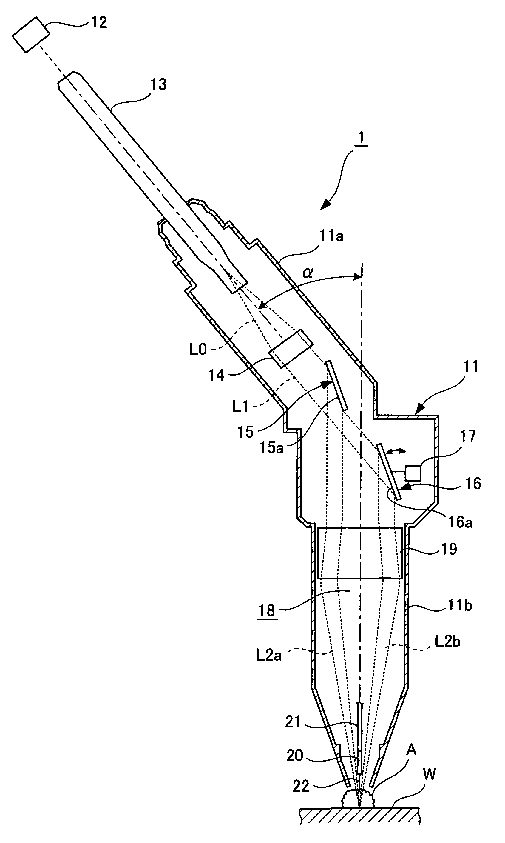
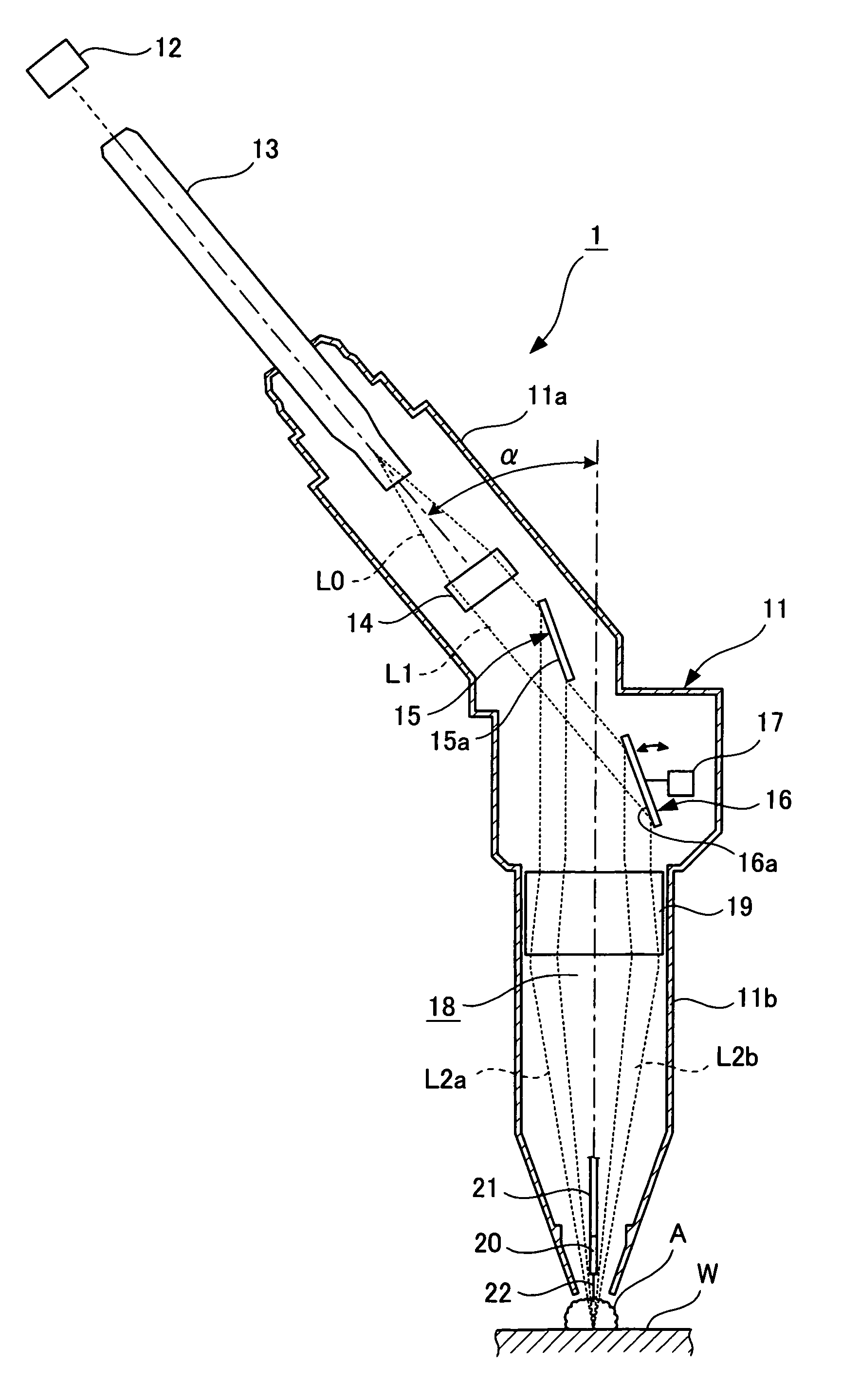
[0021]A laser-arc hybrid welding head according to the present invention will be described in detail with reference to the accompanying drawing. FIG. 1 is a schematic configurational drawing of the laser-arc hybrid welding head according to an embodiment of the present invention.

[0022]As shown in FIG. 1, a laser-arc hybrid welding head 1 according to the present invention has a cylindrical head body 11 constituting a shell thereof. The head body 11 is crooked at its nearly intermediate part, and is composed of an inclined portion 11a on the proximal end side thereof, and a vertical portion 11b on the leading end side thereof, with the crooked region forming the boundary between them. The vertical portion 11b is disposed to have an axis orthogonal to the surface of a base material W, while the inclined portion 11a is disposed to have an axis crossing the axis of the vertical portion 11b at an angle of α (e.g., α=30°).

[0023]To the proximal end of the inclined portion 11a, a YAG laser ...


PUM

PropertyMeasurementUnit
angleaaaaaaaaaa
reflecting angleaaaaaaaaaa
density of energyaaaaaaaaaa

Abstract

A laser-arc hybrid welding head performs laser light irradiation and arc discharge of a base material to weld the base material by combined use of laser welding and arc welding. The welding head includes an optical fiber for transmitting laser light used in laser welding and an arc electrode for generating an arc between the arc electrode and the base material. The optical fiber is disposed such that an optical axis thereof crosses an axis of the arc electrode at a predetermined angle.

Description

BACKGROUND OF THE INVENTION[0001]1. Field of the Invention[0002]This invention relates to a laser-arc hybrid welding head which can weld a base metal material, as an object to be joined, by combined use of laser welding and arc welding.[0003]2. Description of the Related Art[0004]Laser welding and arc welding are available as types of welding technologies for joining a base metal material, which is an object to be joined. Of these technologies, the laser welding process performs welding by focusing laser light on one point of the base material with the use of optical instruments such as a lens and a mirror. According to this process, the density of energy is so high that high speed, low strain welding providing a great depth of penetration can be performed in a narrow fusion range.[0005]The arc welding process generates an arc between the base material and a welding wire, or between the base material and an electrode, fuses the base material by the heat of the arc, and performs weld...

Claims


Application Information

Patent Timeline
Patent Type & Authority Patents(United States)
IPC IPC(8): B23K26/00B23K9/16B23K26/21B23K26/346
CPCB23K9/173B23K26/067B23K26/1429B23K28/02B23K26/0673B23K26/348
Inventor WATANABE, MASAOFUKAMI, KENICHISETODA, KEISHI
Owner HONDA MOTOR CO LTD
Why Eureka
Try Eureka